electric hurdy gurdy synthy | about that seed funding money
2018-07-13 09:39:56
I've spent a little on the motor and you could argue that having a 3D printer might forever factor into your projects.. but since my moob removal surgery (if I just say surgery people ask anyway) I wasn't up to my tinkering game and wasn't working on this. It feels dishonest not to share this and I've made sure an awesome project, the #ZeroPhone - a Raspberry Pi smartphone from this platform got the money instead. @Arsenijs lives for that project and that dedication is what I envy and sometimes lack with my projects. Hope that levels some karma :D
Arduboy MAX | sponsored by aisler
2018-07-12 18:00:22
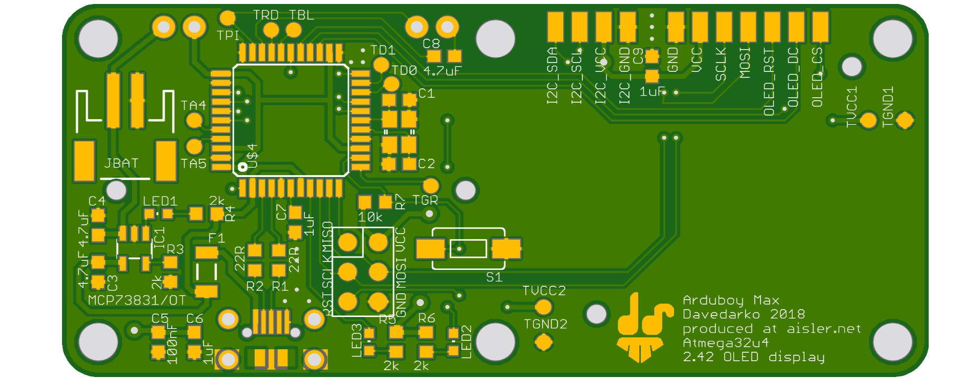
They've contacted me via instagram - like oh so many pcb fab houses do these days - and offered a free run - couldn't say no! I've added test points to attach the RGB LED, not so keen on using it, but wanted to have the option. The display will be soldered via wires. There's no battery protection on it, only a charger. Extra pads for I2C. Additional test points for vcc and gnd. Buttons will be classic Game Boy pads.
K.I.T.T. - KNIGHT RIDER badge/brooch | that shitty add on standard
2018-06-30 17:56:43
I've added a little smd / smt 2x2 header to the badge for future boards, kinda liked the idea to power boards over that instead. Just don't solder the battery holder and the clip and everything should fit.
Maker Faire Berlin 2018
2018-06-02 20:35:18
This year me and @Alex were visiting the 2018 Maker Faire in Berlin together, we've met some youtubers, people known in the hackadayverse, saw some awesome projects and had a lot of fun!
Something that surprised me and made my day: I got recognised from last year where we did the unofficial hackaday.io community stand! I even got a little present as a thank you for when I gave him some PCBs and a hackaday prize shirt.
thanks Paul!
sound button hack | Arduino code
2018-05-19 09:12:01
/***************************************************
DFPlayer - A Mini MP3 Player For Arduino
<https://www.dfrobot.com/index.php?route=product/product&search=mp3&description=true&product_id=1121>***************************************************
This example shows the basic function of library for DFPlayer.
Created 2014-8-28
By [Angelo qiao](Angelo.qiao@dfrobot.com)
GNU Lesser General Public License.
See <http://www.gnu.org/licenses/> for details.
All above must be included in any redistribution
****************************************************/
/***********Notice and Trouble shooting***************
1.Connection and Diagram can be found here
<>
2.This code is tested on Arduino Uno, Leonardo, Mega boards.
****************************************************/
#include "Arduino.h"#include "SoftwareSerial.h"#include "DFRobotDFPlayerMini.h"
// rx 3
#include <avr/sleep.h>#define BODS 7 //BOD Sleep bit in MCUCR#define BODSE 2 //BOD Sleep enable bit in MCUCR#define RX 3 // *** D3, Pin 2#define TX 4 // *** D4, Pin 3
SoftwareSerial softSerial(RX, TX); // RX, TX
DFRobotDFPlayerMini myDFPlayer;
void printDetail(uint8_t type, int value);
void setup()
{
softSerial.begin(9600);
if (!myDFPlayer.begin(softSerial)) { //Use softwareSerial to communicate with mp3.
}
myDFPlayer.outputDevice(DFPLAYER_DEVICE_SD);
myDFPlayer.enableDAC();
delay(200);
myDFPlayer.volume(30); //Set volume value. From 0 to 30
myDFPlayer.play(1); //Play the first mp3
}
void loop()
{
if (myDFPlayer.available()) {
uint8_t type = myDFPlayer.readType(); if (type == DFPlayerPlayFinished) { // sleep(); // myDFPlayer.play(1); myDFPlayer.disableDAC(); myDFPlayer.sleep(); mcu_sleep(); }
}
}
void mcu_sleep()
{
byte mcucr1, mcucr2;
set_sleep_mode(SLEEP_MODE_PWR_DOWN);
sleep_enable();
MCUCR &= ~(_BV(ISC01) | _BV(ISC00)); //INT0 on low level
ADCSRA &= ~_BV(ADEN); //disable ADC
cli(); //stop interrupts to ensure the BOD timed sequence executes as required
mcucr1 = MCUCR | _BV(BODS) | _BV(BODSE); //turn off the brown-out detector
mcucr2 = mcucr1 & ~_BV(BODSE); //if the MCU does not have BOD disable capability,
MCUCR = mcucr1; // this code has no effect
MCUCR = mcucr2;
sleep_cpu();
}
resistor color code watch | first prototype
2018-05-05 18:14:35
So it's pretty tough to show grey vs. white and brown vs. orange and I thought to help with that I'll take a WS2812B 4x4 matrix and make it a binary coded decimal clock.
Pimp my breadboard | Episode two
2018-05-03 10:55:17
I totally forgot that I've created a project for this, but that only shows how important pink breadboards are to me! Here's part two of the series on my endeavour to get some nice breadboards. Next time I'll focusing on the power supply adapters you can get on ebay and will do something fun with them.
I've gotten some input again and will try with more small white breadboards, thankfully they're very cheap on aliexpress - I got ten for 3,4 Euros. I'll experiment with exposure time and a thinner solution.
The solution I've used this time is called "Rit Dye" and is meant for dyeing synthetic clothes and this time it worked well! Thanks to @WooDWorkeR who gave me the link to this https://geekhack.org/index.php?topic=35444.0 I was pretty sure it would work this time and the results look very cool, a bit cherry red because they were probably exposed for too long.
The spray paint doesn't look that bad either but will probably scratched of in the long run.
FAME BOY | FAME BOY - build log 6 - Hack Like Heck
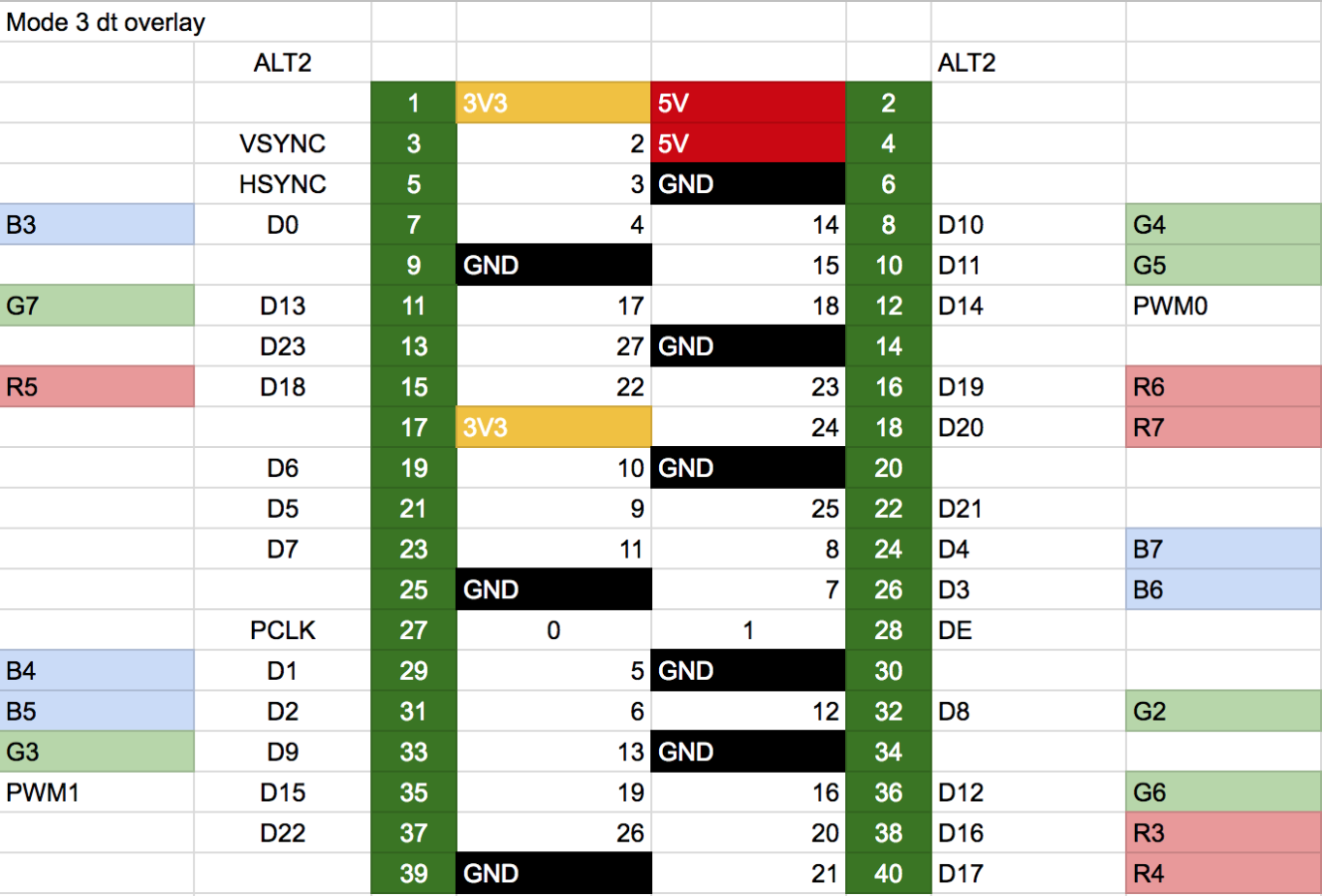
dtparam=i2c_arm=off
#dtparam=i2s=on
dtparam=spi=off

dtparam=audio=on
gpu_mem_256=128
gpu_mem_512=256
gpu_mem_1024=256
overscan_scale=1

# usb network
#dtoverlay=dwc2

# enable the DPI display
enable_dpi_lcd=1
display_default_lcd=1

# Set screen size and any overscan required

overscan_left=0
overscan_right=0
overscan_top=0
overscan_bottom=0
framebuffer_width=480
framebuffer_height=272

# set up the size to 480x272
dpi_group=2
dpi_mode=87

# set up the hsync/vsync/clock polarity and format
dpi_output_format=0x7F013

# set up the size to 480x272
hdmi_timings=480 0 40 48 88 272 0 13 3 32 0 0 0 60 0 9600000 3
FAME BOY | FAME BOY - build log 5 - Hack Like Heck
2018-04-22 12:24:58
I have spent waaaay too much time on the design so far and I'm only at 75% of finishing it. It seems like the parts will arrive this Friday, so it's going to be a long weekend. I've set up a "war zone" for the project, a "FAME BOY only" table of 100 x 60 cm2. Today the button boards arrived from aisler.net, with a bit of drilling and snipping some plastic posts I was able to fit almost everything but the shoulder buttons. I've ordered a set of buttons again, this time in black! Every part you see needs to be reprinted though, to fit the shoulder buttons. I have the shoulder button design ready, and the bottom parts are ready for a draft print as well. I will try to fit everything in and then com back to the design later, when everything is placed.
So back to the "war zone", I need to fix the Game Boy cartridge reader. It won't start with the program but in the bootloader mode and I need to find out what that was all about. Then I can come up with a way to alert the Raspberry PI that there is a cartridge present. I don't have any diodes on the button pcbs, something I now regret because it's going to be tough to just add the cartridge state as one of the buttons. Ghosting could get tricky.
FAME BOY | FAME BOY - build log 4 - Hack Like Heck
2018-04-22 12:23:38
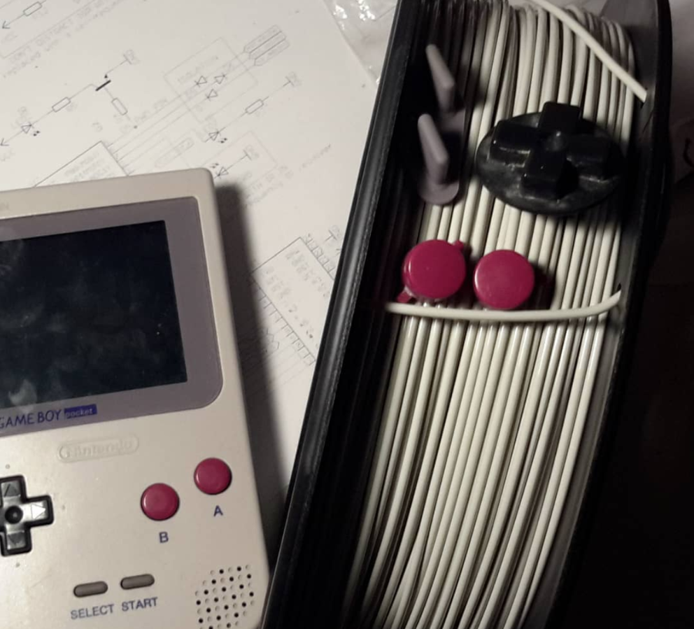
What a perfect fit of colors, but sadly this PLA wont print on both of the companies Zortrax M200. There's an option to load external materials on the Zortrax M200 for a while now and I was too shy to test it out (Zortrax is closed gcode and was closed filament). Since I've printed with PLA on my 2014 printrbot simple already, I didn't think there could be too many problems though and so I did a little trip to 3dk.berlin, that was 4 metro stations away from home. Sadly the printer won't even load the filament and after asking around in the zortrax user group on facebook it turns out that you have to use a hotend+nozzle purely for the PLA for "best results". Well no, I'll just use one of the white tones in the material that I know prints and have laying around. Bummer, had a great time in the store. Let's talk about getting a CR10 + custom color PLA after the contest.
[update] the acrylics for the screen protector went to my parents place instead to me. They were not there to receive it and the shop it went to is only open from 10 to 5, Monday through Friday. The eBay person was good enough to resend it though, so I can expect it to arrive on Thursday, almost a delay of one week.
FAME BOY | FAME BOY - build log 3 - Hack Like Heck
2018-04-22 12:22:11
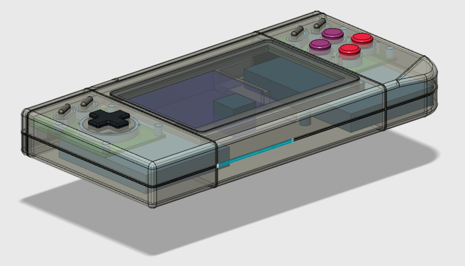
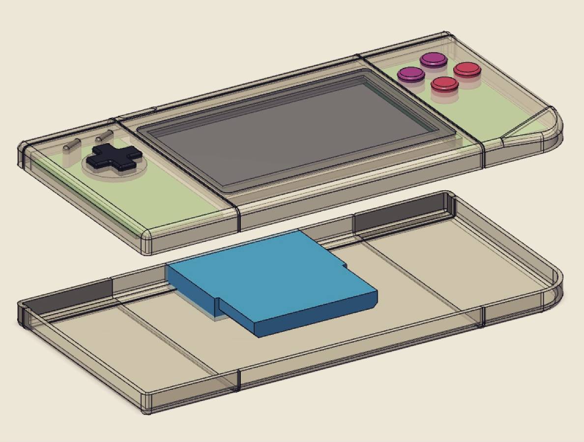
Still looking for the right material to print the case in, but on Saturday I will go to the store of a local filament maker, worst case scenario they could mix up a DMG colored PLA plastic. But I'm sure I'll be happy with one of their 5 greys they have in store so I don't have to pay 240 Euros for 5kg of filament. I also spoke to a friend of mine who works in the copy shop I used to work and he had some great ideas about the screen bezel. I might be able to grab some better new buttons and silicone pads as well. Exiting stuff! Here's a current "render" of the case, I've placed the raspberry pi on the left side and the battery pack on the right. I'm a bit worried about it not being well balanced and I'll have to see about that when I have the rest of the parts.
FAME BOY | FAME BOY - build log 2 - Hack Like Heck
2018-04-22 12:21:18
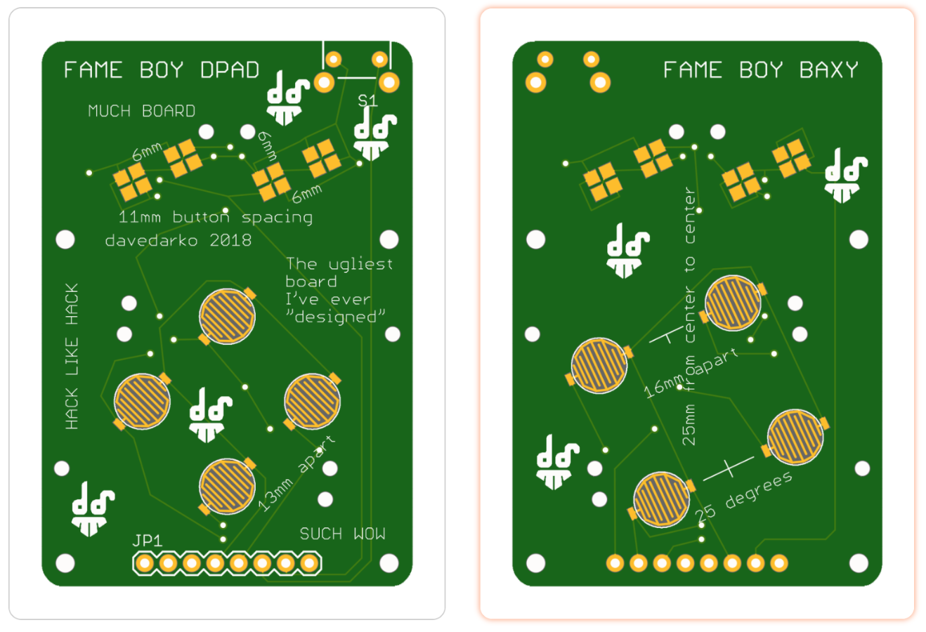
Much buttons - such board
I'm done with the boards for the buttons! that's the most sloppiest board I've ever "designed". My main focus was on getting the dimensions for everything right. Hopefully every plastic nibble has the corresponding drill hole. The angles should be right. The shoulder button might be on the wrong side of the board, but maybe it's just right for the biggest lever I could achieve with the buttons. Boards are ordered from aisler.net, a German oshpark.com "strive to be", hopefully the boards will get here within the next week. Designed with EAGLE, because there was no time to learn to do that in KiCad (I notice a theme here).
I hope I get this project done before my sister arrives, she will visit our home town right days before the end of this contest, so I need to steal some time before that. Now it's back to waiting for the results and further designing on that case design. From there it should be mostly soldering and programming that I can do from anywhere.
Thank you for reading this short log! I hope the naming choice is quite obvious by now - I started with my LAME BOY that had a lower resolution than the GAME BOY, so it's lame. The FAME BOY purely exists to become famous like Ben Heck - a vanity project to gain subscribers Well I wouldn't have started something like it at least and this contest is about becoming a paid youtuber somewhat. Not so many choices with naming to come after that.
FAME BOY | FAME BOY - build log 1 - Hack Like Heck
2018-04-22 12:17:42
[blatently copied from e14]
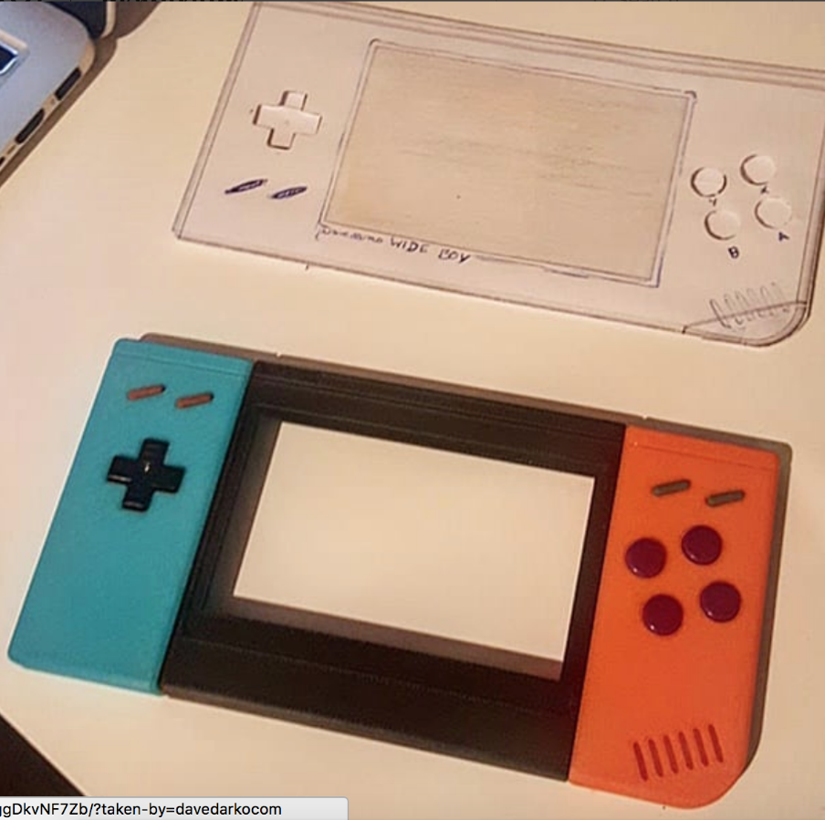
Okay, wow - the competition is strong. So I thought in case I'm in the TOP10, I'd use that sweet screen and go another route, instead of using a classic DMG case! Here's a mockup of what I'd like to do, drawn in 123D Design, since I doubt there's enough time for me to learn fusion360 and finish the design in it. The cartridge reader is supposed to fit classic Game Boy cartridges and Advance games, therefor the dummy cartridge is a mix of both. This design is 20cm wide, so to prevent warping and early release from the build plate, I'm going to spilt it up and make it modular, but the controllers wont come of. While looking for pics of the switch, I sadly found a similar design rendered by an artist. But I guess that happens to every one and I like the design and want to go no with that. There will be shoulder buttons, too. let's see if I can fit everything inside and how thick it will be in the end :)
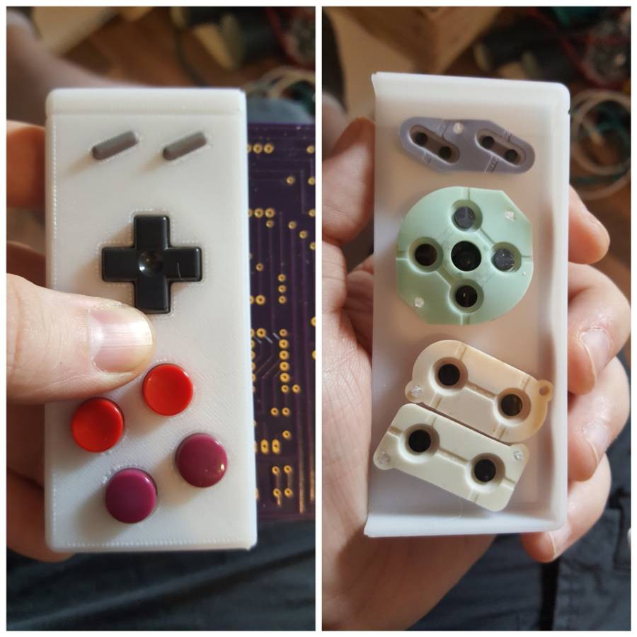
Here is a test print of the controller buttons, all on one side, just to check how the buttons are fitting. With some minor tweaks this should be perfect!
Pimp my breadboard | Episode one
2018-04-22 08:37:07
Yesterday I was filming me trying to use a textile dye to get a different colored breadboard and also tried to bleach a red breadboard into something more pinkish. There will be more tests, also got some great ideas and input.
on the 13th of May the winners of the BOM auditions were announced - on the 23rd the parts are expected to arrive here in Germany (send today, national winner packets were send on last friday). My plastics for the screen bezel were supposed to arrive last friday, hopefully it will get here on thursday. Ebay decided to redirect it to my parents place, so we had to resend it cause the dropoff place is open from 10 to 4... argh. I'm trying to print ABS now, seems like I have killed the hotend with the attempt to print with PLA.
Meh.
FAME BOY | feels a bit empty, for reasons
2018-03-18 18:54:11
There was an unofficial statement of "bonus points for blog posts" on the element14 community page for the "Hack Like Heck" contest, so that's why I'm posting my logs there and I'm too lazy to copy them over here. Wouldn't feel right either, so I admit to being lazy.
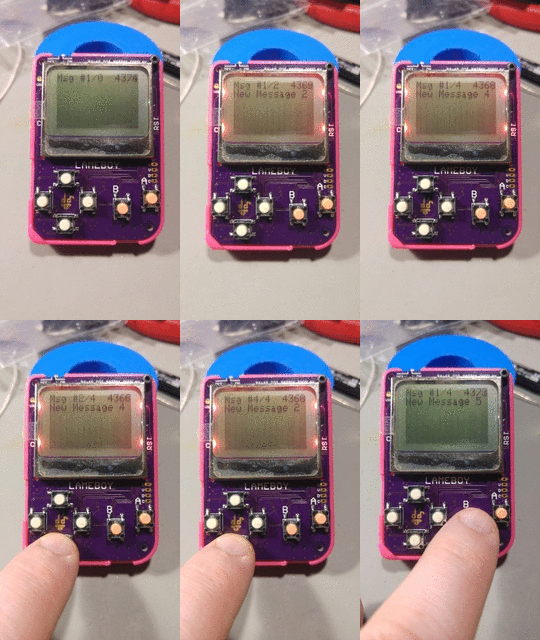
I've wanted to build myself a small MQTT based message reader like those majestic 90s pagers everybody lusted after back then and I have a Lameboy. So I knew what i had to do.
This "mod" does consist of 2 parts, a little hardware upgrade and a very small firmware.
---------- more ----------
The Hardware
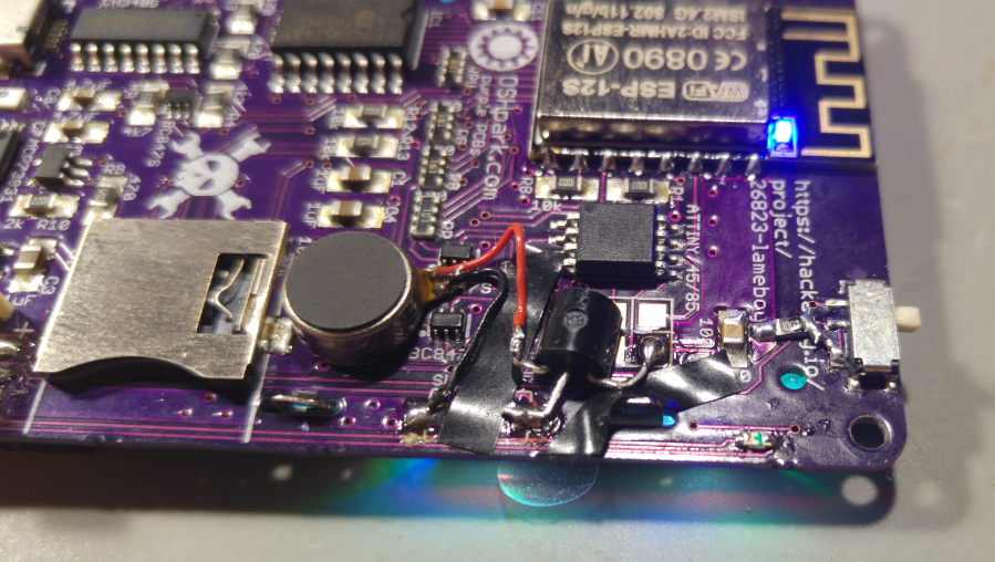
All we need is an NPN-transistor and a small vibration motor (+ something to glue it to the Lameboy)
The Lameboy has 2 visible Action Buttons, the A and B button. But there is also a C button hidden on the backside/inside of your little Lameboy and thanks to the magic of the I/O expander used, this button will be an OUTPUT!!!!
We add an NPN Transistor with its base connected to the C-Button pad, collector to 3.3V and the emitter to the positive side of our vibration motor. And the negative side of the motor we just solder to ground.
Now i have my very own small and simple MQTT based pager \o/
electric hurdy gurdy synthy | 3d printing stuff
2018-03-17 11:56:51
currently printing all of this, I already forgot the tooth count and ratio of the gear box, but I think it's something like 1:5 or 1:6. Or maybe it was 1:10. Reminds me a bit of my #Locomatrix - 3D POV - a different approach