electric hurdy gurdy synthy | I've bought a brushless motor
2018-03-15 19:17:45
now what? I need to do some experiments, find out what speeds I need, what kind of gearboxes make sense etc to get the most our of the motor. There are chips like LM74670 that together with a MOSFET can replace diodes for creating a rectifier. First thing that needs to be done is a small gearbox and crank.
The LT4320 (I'd need three of them) is around 6 Euros each. Ouch.
Me: I have this project idea: #WIFI Game Boy Cartridge - I was a bit naive when I started this, tried to toggle pin for pin but it was way too slow. Would/could this work with the I2S parallel interface? I wasn't able to find much on the I2S interface when I started this and what I found was above my skill set, but I still like the idea of having a cartridge that has wifi.
Sprite_tm says:4:31 PM Ah, I saw that. Did something like that on a Vectrex with a CortexM4.
Sprite_tm says:4:32 PM Wrt the WiFi GB cartridge: Long story short, I don't thing I2S is the right way to go there.
Me: okay, any right ways?
Sprite_tm says:4:33 PM The issue mostly is that you need to see that a CS line goes low, then immediately read the address lines, look up whatever you want to send back and send it.
Sprite_tm says:4:34 PM I think that I2S would be too slow for that; you'd have to set up a transaction and everything. I think you could get it to work if you wrote a high-prio interrupt for the CS pin, then in the interrupt handler, in assembly, read the address GPIOs as fast as you can, grab a response from internal memory (which luckily you have more than enough of) and send that to the data pins.
Sprite_tm says:4:35 PM If you need help with that, poke me; by now I have some experience with high-level interrupts and I'm actually curious if the ESP32 can do it, but don't really have any interesting consoles here.
Me: I thought "as fast as I can" would be I2S, since there's no way of getting pins parallel
Sprite_tm says:4:37 PM You might get it to work... but there's a fair amount of setup using the I2S peripheral. It may still be quicker than doing it manually, I agree.
Sprite_tm says:4:39 PM @davedarko Maybe a good idea to move on to other qs... if there is still time at the end, I'd love to come back to it. For now, feel free to poke me at [mail] for this.
well, who needs one anyways? I plan on backing up stuff from here with the help of the API. My old content is converted to the new "engine". Everything is now backed up in github, I have version control and am able to rework some content.
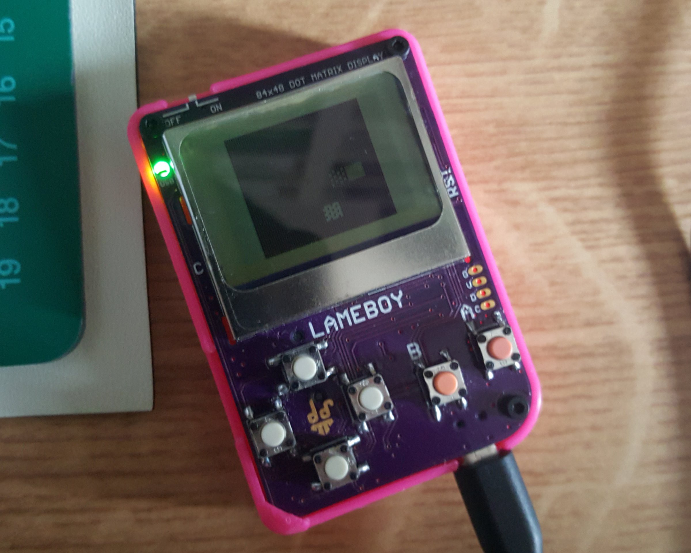
LAMEBOY - another ESP12 handheld | customised spacehuhn case
2018-02-25 17:11:21
I've used a 3D printing pen to test if I could do some inlays with that - I think it worked out reasonably well :)
LAMEBOY - another ESP12 handheld | CircuitPython on the Lameboy
2018-02-23 09:25:42
Here are some commands you need to get started to install circuit python and snake on @ɖҿϝիɟթվ s #PewPew FeatherWing engine. How awesome is that :) You can also follow along Radomir's description, which is way better.
sudo esptool.py -p /dev/cu.wchusbserial1410 erase_flash
sudo esptool.py -p /dev/cu.wchusbserial1410 --baud 115200 write_flash --flash_size=detect 0 adafruit-circuitpython-feather_huzzah-2.2.3.bin
// deactivate esp debug to serialimport esp; esp.osdebug(None)
ampy -p /dev/cu.wchusbserial1420 ls
ampy -p /dev/cu.wchusbserial1420 put lameboy.py
ampy -p /dev/cu.wchusbserial1420 put pew.py
ampy -p /dev/cu.wchusbserial1420 put snake.py
ampy -p /dev/cu.wchusbserial1420 put menu.py
ampy -p /dev/cu.wchusbserial1420 put main.py
// in case of errorsimport os; os.remove('main.py')
// change attiny i2c adress to allow comsimport lameboy; lameboy.i2c.writeto(0, b'A\x0d\xd0\x0d\x0d')
sloth badge | new design!
2018-02-20 23:59:57
After a fallout with pimoroni I'm no longer allowed to use the sloth badge design. So here is the new design:
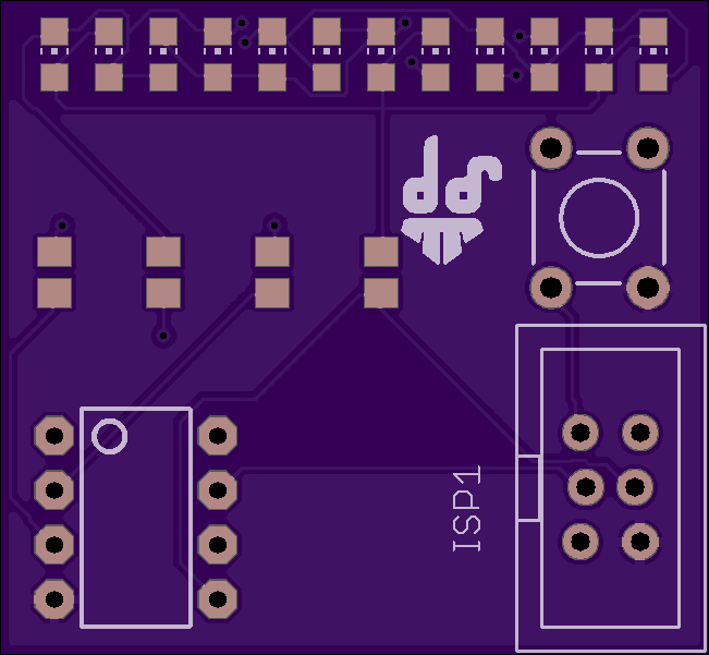
Just kidding! I've bought a soic8 adapter that I will solder into place and make this a dedicated SOIC8 programmer for the kit chips! I haven't heard from pimoroni in a while though, need to ping them in a tweet some time.
LAMEBOY - another ESP12 handheld | Changing the address of the Attiny
2018-02-20 22:17:12
[UPDATE] I've soldered up another Lameboy and checked the behaviour in Arduino, tried sending data to 0x0d but nothing happened. I've then set the address to 0x0d and it works with that address. Seems like it won't be written to the EEPROM on init but later checks the EEPROM for an address. (btw., I've edited the range for scanning from 1-255 to 0-127). It's probably still a different experience with python.
Thanks to Radomir @ɖҿϝիɟթվ who read through the cyz_rgb code and found the procedure, it's now possible to set the adress of the blinkM clone to a "real" legal value. This is how you'd do that in Arduino. After that it's stored into the EEPROM of the attiny. I'll do that for the next kits that go out.
void setAdress(byte a)
{
  // A X D0 0D X
  Wire.beginTransmission(0x00);
  Wire.write('A');
  Wire.write(a);
  Wire.write(0xd0);
  Wire.write(0x0d);
  Wire.write(a);
  Wire.endTransmission();
}
LAMEBOY - another ESP12 handheld | R3.1 boards in the wild
2018-02-20 09:55:04
So before I started selling on @Tindie , I was sending off a kit to @ɖҿϝիɟթվ and I forgot to send him a crystal with that kit / check all the content before sending. There are also two fully assembled versions out there now, one has an ESP chip with 2MB flash instead of 4MB. From then on every ESP12 module is checked before sending.
So here's rule number one:
Use the checklist and check if every part is in the kit. Obviously.
Known issues number one is the enable pin of the power regulator is floating, you need to botch the 10k to the switch.
I will modify all future / rest of the pcbs so it's clear where to put it
missing markings for RGB LEDs, the dot points towards the USB plug
the charging indicator LED - minus points towards the USB plug
power muxing chip pin 1 points AWAY from USB plug
There is no test program that greats you with a "hooray, you've made it".
flash the ESP with a basic code, flash RGB lights, check buttons and display
Change the I2C address of the attiny before shipping
to be continued...
team badge idea | protoboard draft
2018-02-19 23:29:09
The ArduinoISP with all the LEDS, routed for soldering comfort, we'll fix that in software.
One of the four attiny45 Segments with IR communication.
The hole pcb.
sloth badge | current code, anyone any ideas to save space?
2018-02-19 11:28:26
I won't lie, this feels messy. This currently features 5 animations, where 2 of them are just "played accelerating" .
Some things I'm not happy with:
- the button does not work within the animations, so you need to push the button until the animation cycle is over
#include <avr/sleep.h>#define nop() asm volatile("nop")
boolean leds_on = true;
byte badly_programmed_counter = 0;
byte animation_counter_max = 5;
byte animation_counter = 0;
// we need two frames with 8 bits for 12 LEDs
byte frame1 = 0;
byte frame2 = 0;
// animation where every third LED is glowing
// I could shift that continuosly and drop 4 bytes
constbyte three_apart_length = 6;
constbyte three_apart[three_apart_length] PROGMEM = {
0b10010010, 0b01000000,
0b01001001, 0b00100000,
0b00100100, 0b10010000,
};
// this one is huge
// is there a math function to do that instead?
constbyte updown_length = 14;
constbyte updown[updown_length] PROGMEM = {
0b00100000, 0b00000000,
0b01010000, 0b00000000,
0b10001000, 0b00000000,
0b00000100, 0b00010000,
0b00000010, 0b00100000,
0b00000001, 0b01000000,
0b00000000, 0b10000000,
};
// that's just blinking each led
// maybe inverting the data bitwise does the trick
constbyte two_apart_length = 4;
constbyte two_apart[two_apart_length] PROGMEM = {
0b10101010, 0b10100000,
0b01010101, 0b01010000,
};
// should have taken a switch, sleep stuff is huge
ISR(INT0_vect) {
sleep_disable();
leds_on = true;
}
voidsetup(){
// this is for the button setup
PORTB |= (1 << PB1);
DDRB &= ~(1 << PB1);
shutdown_chip();
}
voidloop(){
if (leds_on)
{
cli();
leds_on = false;
// I call it that, because the millis stuff
// and the interrupts collided and broke
badly_programmed_counter = 0;
}
// fancy way of checking the button state
if (!(PINB & (1 << PB1)))
{
badly_programmed_counter++;
my_100ms_delay();
// check if button was released before time
// so animation index can be incremented
// maybe a modulo with animation_counter_max
// safes space
if ( (PINB & (1 << PB1)) )
{
badly_programmed_counter = 0;
animation_counter++;
if (animation_counter == animation_counter_max)
{
animation_counter = 0;
}
charlie(animation_counter);
// calling a function instead of writing it down
// 5 times helps already
for (byte b = 0; b < 5; b++) my_100ms_delay();
}
if (badly_programmed_counter >= 7)
{
// blink when shutdown is immanent
for (byte b = 0; b < 5; b++) blip();
shutdown_chip();
}
}
else
{
animate_leds();
badly_programmed_counter = 0;
}
}
// this is probably already at it's best
voidcharlie(bytevar){
leds_off();
switch (var) {
case0: // 1
DDRB |= (1 << PB0) | (1 << PB2); // output
PORTB |= (1 << PB0); // HIGHbreak;
case1: // 2
DDRB |= (1 << PB0) | (1 << PB2); // output
PORTB |= (1 << PB2); // HIGHbreak;
case2: // 3
DDRB |= (1 << PB2) | (1 << PB3); // output
PORTB |= (1 << PB2); // HIGHbreak;
case3: // 4
DDRB |= (1 << PB2) | (1 << PB3); // output
PORTB |= (1 << PB3); // HIGHbreak;
case4: // 5
DDRB |= (1 << PB3) | (1 << PB4); // output
PORTB |= (1 << PB3); // HIGHbreak;
case5: // 6
DDRB |= (1 << PB3) | (1 << PB4); // output
PORTB |= (1 << PB4); // HIGHbreak;
case6: // 7
DDRB |= (1 << PB0) | (1 << PB3); // output
PORTB |= (1 << PB0); // HIGHbreak;
case7: // 8
DDRB |= (1 << PB0) | (1 << PB3); // output
PORTB |= (1 << PB3); // HIGHbreak;
case8: // 9
DDRB |= (1 << PB2) | (1 << PB4); // output
PORTB |= (1 << PB2); // HIGHbreak;
case9: // 10
DDRB |= (1 << PB2) | (1 << PB4); // output
PORTB |= (1 << PB4); // HIGHbreak;
case10: // 11
DDRB |= (1 << PB0) | (1 << PB4); // output
PORTB |= (1 << PB0); // HIGHbreak;
case11: // 12
DDRB |= (1 << PB0) | (1 << PB4); // output
PORTB |= (1 << PB4); // HIGHbreak;
default:
;
nop();
}
}
voidshutdown_chip(){
animation_counter = 0;
leds_off();
/* Clear WDRF in MCUSR */
MCUSR &= ~(1 << WDRF);
/* Write logical one to WDCE and WDE *//* Keep old prescaler setting to prevent unintentional time-out */
WDTCR |= (1 << WDCE) | (1 << WDE);
/* Turn off WDT */
WDTCR = 0x00;
ADCSRA &= ~(1 << ADEN); // turn off adc
GIMSK |= (1 << INT0);
GIMSK |= (1 << PCIE);
set_sleep_mode(SLEEP_MODE_PWR_DOWN);
sleep_enable();
sei(); // Enable global interrupts
sleep_cpu();
sleep_disable();
}
voidanimate_leds(){
switch (animation_counter)
{
case0:
animate_frames(
three_apart_length,
three_apart,
512
);
break;
case1:
for (byte acc_counter = 1; acc_counter < 64; acc_counter += 2)
{
animate_frames(
three_apart_length,
three_apart,
acc_counter * 8
);
}
break;
case2:
animate_frames(
updown_length,
updown,
512
);
break;
case3:
animate_frames(
two_apart_length,
two_apart,
2048
);
break;
case4:
for (byte acc_counter = 1; acc_counter < 64; acc_counter += 2)
{
animate_frames(
updown_length,
updown,
(63-acc_counter) * 4
);
}
break;
default:
leds_off();
break;
}
}
voidanimate_frames(
byte animation_length,
constbyte* animation_array,
uint16_t frame_duration
){
for (byte i = 0; i < animation_length; i += 2)
{
// save the last time you blinked the LED
frame1 = pgm_read_byte_near(animation_array + i);
frame2 = pgm_read_byte_near(animation_array + i + 1);
show_frame(frame_duration);
}
}
// this just looks ugly, but needs to be done
// for loop through frame bytes to set the LEDs with
// the charlie plex function
voidshow_frame(uint16_t byteframe_length){
for (uint16_t j = 0; j < byteframe_length; j++)
{
//iterate through bit maskfor (byte i = 0; i < 12; i++)
{
// if bitwise AND resolves to trueif (
(
i < 8 &&
1 << i & frame1
) ||
(
i > 7 &&
1 << (i - 4) & frame2
)
)
{
charlie(i);
}
else
{
charlie(255);
}
}
}
}
voidleds_off(){
DDRB &= ~(0b00011101);
PORTB &= ~(0b00011101);
}
voidblip(){
charlie(11);
// delay(100);
my_100ms_delay();
charlie(255);
// delay(100);
my_100ms_delay();
}
voidmy_100ms_delay(){
for (uint32_t i=0;i<40000;i++) nop();
}
LAMEBOY - another ESP12 handheld | the quest for sound
2018-02-15 12:55:00
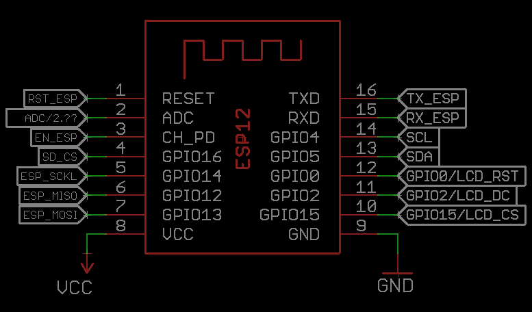
I'm currently looking into getting a sound pin and the most likely candidate right now is the LCD reset pin. Did anyone ever had any problems not using the reset pin of the Nokia LCD? What could I test to make sure it works fine? worst case scenario is turning the lameboy on and off again, I guess. I could try using RX and TX for sound, where depending on the TX state the RX would emit sound (no modem noises while uploading if done right). But if I could free the RST pin for sound, then I could use the same idea for RX and TX to transmit IR maybe. Would be cool features to have, I think.
Also to consider:
using the D/C pin of the display for other things, maybe move to TX
a "true" in system programmer | thoughts after half a year
2018-02-14 11:37:00
Overall I'm pretty happy with it, but I'm a bit sad that I can't use this with boards where pinheaders are already present. Would have been nice to have a standard 2x3 ISP socket on it and change between cables, pogopins and avr clamps. When it comes to power, a little regulator for 3V3 would be nice too. Basically switch between 5V, 3V3 and selfpowered.
K.I.T.T. - KNIGHT RIDER badge/brooch | 0603 revision of the code
2018-02-02 21:04:15
Recently on twitter Jon Raymond asked about a firmware update for the older versions of the badge. My hesitation was big until this point, since I thought the charlie-plexing would take up too much space alone, to integrate animations like I did with the newer 0805 version of this badge. As you can see here, I've logged a bit about the progress over on twitter https://twitter.com/davedarko/status/959491261903310848.
I was able to put 7 animations onto the badge! If you want to try out some other animations on the push of a button, you now can!
added 7 animations, cycling through on push of a button
removed digitalWrite and pinMode functions and replaced them with setting appropriate registers
converted every int to 8bit / 16bit unsigned integers where I could
Download the hex - file from the download section and upload it to the attiny via:
You need to solder a button between the PB4 Pad and GND and find a good spot to glue it down. Have fun :)
slow chaser
fast chaser
K.I.T.T. persistance of vision (I'm really bad at this)
cross fader
cross fader beam
police flasher
computing (counting up in binary)
link drop for modding/repairing/hacking stuff | IKEA Tjena boxes
2018-02-02 13:29:17
I use them for storing my projects, most of them fit just fine. The newer versions don't come with the cool sticker backside where the label goes in, so I had to research the dimensions etc, only to find out that there is a label to cut out of the instruction manual - but who reads that, right? :D Anyway, here are the dimensions of the label that I found out. Would be cool to find a label generator of some sort.
Spacehuhn badge | Finished painting the set
2018-01-26 14:58:47
I've decided on using the edding 4200 series on this run. I had to go over twice to get a good covering. Next time I'll try nailpolish though, since the color is still removable with Isopropanol, but tougher than with the 300 series.
PWNed the PWNer
2018-01-16 18:52:17
So recently I thought about if it would be possible to have an ESP8266 module troll a "basic settings" deauther by @Stefan Kremser - turns out it is :) I'm a bit proud over here.
I'm currently deciding between 3mm / straw hat / 5mm LEDs and whether the animation should be slow or fast. I could only find 5mm RGB flashers that are diffused, but it would be so cool to have the other ones diffused as well. So I've ordered a bunch (way too many) LEDs and hope they'll arrive soon.