K.I.T.T. - KNIGHT RIDER badge/brooch | 0805 are coming to tindie in 2018
2017-12-29 22:03:08
also, new firmware :) I've somehow managed to add 5 animations and a switch button to toggle between them! all still fits into the attiny13a.
sloth badge | ahhh... I need help, I don't see it
2017-12-09 23:53:17
Somewhere along I had it go to sleep just fine, but it didn't wake up. Now it wakes up fine, but doesn't want to go to sleep. Seems like I don't have the millis stuff right anymore, I don't get to where the comment "// HOW DO I GET HERE?" is. Too tired to see it,
gonna go to bed.
I bought two of these totally hackable current meters: https://www.conrad.de/de/energiekosten-messgeraet-basetech-em-2000-integrierte-kindersicherung-1302517.html at the mini maker faire in Berlin that is this weekend, heavily sponsored by Conrad Electronics. Probably the best about the whole mini maker faire :D @al1 was there too, so that was nice :) We laughed about the whole "wanting to be a big event" feeling, sadly there weren't many visitors around. We've met some cool people though and talked a bit and got two or three ideas for new projects. There was also no lottery to win a DJI spark. That would have been cool, without much competition.
LAMEBOY - another ESP12 handheld | kits
2017-12-01 16:23:33
I'm slowly starting to buy parts for 12 kits. I have a list of people who are interested already and will contact them, once I have everything. It takes me longer than I would have wanted, some financial mishaps are forcing me to not spend money on that. Instead I started selling stuff on tindie, to get some money in again. I've been to a hospital in America, everything is alright, but I had to pay 3 bills upfront before I get all the money back from my insurance. This also is under control, just sucks to watch out not spending too much on stuff.
[UPDATE] seems like I only need 100 Ohm and 150 Ohm resistor arrays, but sadly I had no luck so far getting them in Germany. Only on aliexpress I found some and they usually take a long time to arrive here. No luck on eBay. Also I'm not sure I really need resistors on the green and blue LEDs anyway, since their forwarding voltage is 3.3V at 20mA.
[UPDATE] Thanks to my recent work on #ESP8266 RFid reader I've noticed that the regulator needs to be pulled low, you can't just let it float - which makes perfect sense thinking about it. So that needs to be botched with every version now, but the files are updated. For kitting things up, I need to make sure that everyone is clear on what is what and where to put it. It's complicated and frustrating for sure, hope to make it easy enough though, since selling finished ones seems not an option atm. - German laws... always complicating stuff ;)
seems like they use 1.1mA in sleep mode, which isn't really good for a coin cell that has around 230mAh of power - 9 days of doing nothing o.O so with the right settings my sloth badge will already last a lot longer! nice :3
K.I.T.T. - KNIGHT RIDER badge/brooch | Sunday is fun day :)
2017-11-19 13:54:12
had some fun with my cell phone, a ukulele and a soldered badge in the wild :)
Oh help me Michael Knight! So this started yesterday and I just finished a box of 20 "badges" (gotta be careful around here what to call badge and what not). Some conclusions for the next badge, if I ever tend to be so crazy:
only do ten at a time
change footprint to 0805
there's a spare pin that could run through some modes (fast, slow, pov)
Change to two leds per pins
I stole the idea of processing from tymkrs.com where they put together 10 badges at a time with the help of a lazy Susan. Pretty cool idea and it worked great (unless I forgot I can rotate the assembly line).
So 7 hours of production and I was able to take this picture:
Now I'm off to @Tindie and see that I can put up a store etc. I don't have 0603 resistors for kits yet, once they're here I will put up kits as well. Any tindie tips?
LAMEBOY - another ESP12 handheld | finding the right connector for I2C
2017-11-17 11:34:05
The whole reason I'm looking for something else: I wrote seeed studio about getting the SMT version of the grove connector and they told me that they're sold out / not in stock anymore. I tried a JST 2mm 4 pin connector, but it's just a pain to connect. To be continued, but please, feel free to comment ideas. I need to find a connector that is:
cheap to find / buy
is well supported with modules
easy to connect
shouldn't break stuff if mistaken for something else
easily obtainable cables with no soldering involved
USB
there's already a usb port on the LAMEBOY and I don't want people to mixup stuff
TRRS
would be nice, but I don't want to short stuff by accident or have users mistake it for the headphone plug - especially if there's no audio on board.
RJ12 / RJ25 / RJ10
that was actually already proposed to me in a twitter comment (@gsreynaga) use the same stuff that LEGO, http://wiki.makeblock.cc/index.php?title=RJ25_Wiring_System and probably others. So right now I'm leaning towards RJ10, a 4P4C cinnector, that is also used to connect phones to the speaker+mic part.
MOLEX / 2.54mm connectors
Down in the comments Molex adapters and CD rom cables (basically 2.54mm headers) were suggested, I like the hacker-ready approach, but it doesn't feel like a "finished" design that I want to achieve with revision 4. The current boards have the grove connector still on them.
another suggestion from twitter, use spring connectors. interesting, easily plug and play ready and probably accepts pcbs, if done right. using pcbs as connectors is the cheapest thing I can think of :D https://t.co/taDxle3lOT
I2C peripherals based on Attiny85 (mostly) | aisler boards are here
2017-11-14 22:47:38
Boards are here and although they have some mouse bites, they do fit nicely :) Already soldered one up and it works nicely! Now I only need to write an 8 player game to fully make use of them :D
LAMEBOY - another ESP12 handheld | woah - updating from SPIFFS
2017-11-14 21:15:29
So I had the Ghost "game" on my lameboy, put the hudy/ninja puzzle game binary that I've exported from arduino into the spiff and was able to update my lameboy firmware from the spiff. So that's a start and could be incorporated into every game / app via a library of some sorts. Some kind of menu could help you go through the SD card, load firmware into spiff and then update the whole thing. Now I'm fiddling with switching images etc.
Got it working, I can now switch between a menu image and a game image. Woot :) With that my sketch size is limited to half a megabyte (or a bit less), since it's working like the ArduinoOTA library. It reads stuff into the 2nd half of the active 1MB flash and after restart the eBoot bootloader overwrites the firmware. Since this is supposed to be working with Arduino (not just because of me :D) so that people can easily work with it, I just need to take that as a given. There's probably a way to work with rboot, but I'd rather cross that bridge only when I come to it. Cool. Cool, cool, cool.
One quirk: I had to remove SD card support, since it also defined a File. I need to take a look into that later. It probably makes sense to have a menu that allows for upgrading / updating from the SD card. I need both libraries If I want to get out of the games that also use the SD card as well.
Recently I've started a revision 3.2 that turned into a 5.0 revision - in other words it escalated quickly. In the end I had the game boy pocket buttons integrated, changed the CH340G to a CN2102 serial converter, removed the RST and C buttons, moved the I2C port and changed the footprint, changed the footprint of the PCF8574 to a smaller one. Ah, and I ALSO RIPPED UP ALL THE WIRES :D so in the end I closed eagle and called it a waste of time, but didn't delete it. Only 124 airwires, nothing a long weekend can't fix ;)
LAMEBOY - another ESP12 handheld | external gamepad
2017-11-03 08:13:18
I thought about recycling Game Boy Pocket buttons and silicone pads for the Lameboy, but didn't want to redesign the boards just yet (again). So I thought about a little gimmick: why not make a testboard for a little external controller for multiplayer stuff :D it's read out over I2C (with another PCF8574 on it). There's also a race, I've ordered the boards at oshpark and aisler to compare times. I hope every hole is matching the printed things.
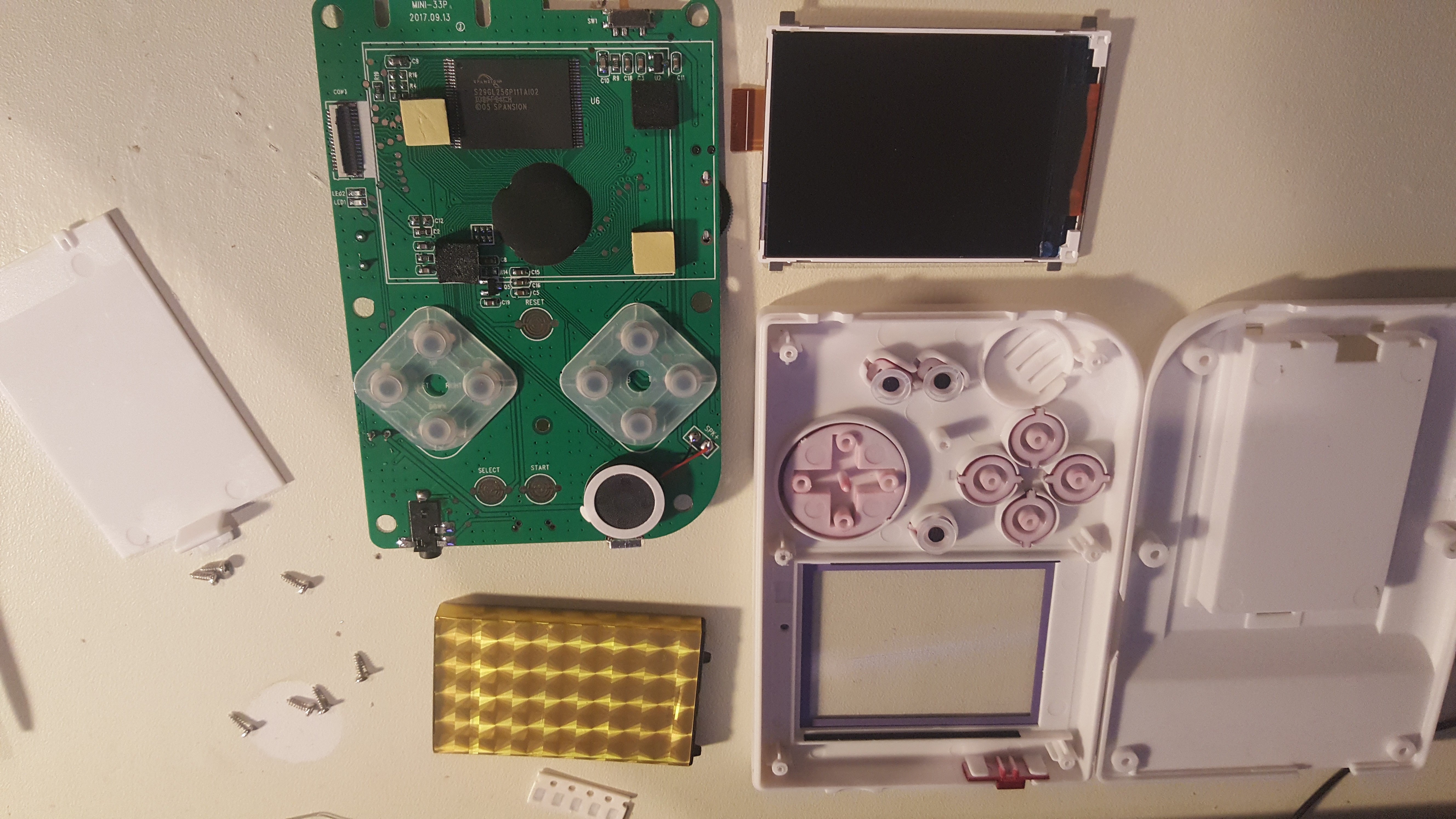
LAMEBOY - another ESP12 handheld | teardown of bittboy
LAMEBOY - another ESP12 handheld | fixing rev2 board bug
2017-10-30 23:02:09
so far I only know of @zakqwy ho ordered boards from that rev, but if there's anybody else out there, here's how to fix it, just connect the pads marked with an arrow with a bodge wire.
LAMEBOY - another ESP12 handheld | sunday inspiration
2017-10-30 01:06:10
Played around with tiles and creating characters today. monochrome 8x8 characters are hard, but I found some cool designs from pico-8. Pretty neat stuff.
LAMEBOY - another ESP12 handheld | working on game mechanics
2017-10-28 23:51:29
I wanted to try out different techniques and tried to replicate the "experience" of the Game of the last log. I got away with a 320x320 pixel tile. The drawBitmap function of the display library seems to do something right :) so no tile engine seems to be needed, but I'm interested to see how @Radomir Dopieralski is doing it over at https://hackaday.io/project/27629-game/log/69791-inside-a-tile-engine
LAMEBOY - another ESP12 handheld | found a cute game
2017-10-28 12:51:14
I haven't seen this before, it's an orthographic "3D" version of pac man on a ZX81. This might just fit perfectly on the LCD! (anyone who wants to program that? :D)
any ideas are welcome, if you can think of an interesting game that might work on a monochrome display, please comment. Nokias Space Impact would be cool to have too.
LAMEBOY - another ESP12 handheld | SSD1327 grayscale display board
2017-10-28 01:43:39
So the SSD1327 grayscale display that I found on aliexpress.com is parallel only (8080 protocol). The chip itself is able to talk I2C and SPI as well, but the protocol select pins aren't broken out on the cable. Since I've ordered a display before I realized that and now that aisler has free shipping I designed a breakout anyway. Also on the board: a 15V step-up converter based on the MT3608 - that converter you get when you search for "12V step up" on eBay and sort by "price+shipping lowest first". Plus my new logo design :) I need a different micro controller for that.
I2C peripherals based on Attiny85 (mostly) | starting point for I2C sound card
2017-10-26 23:43:14
After posting, let me quickly remove the SID part and hope no one ever saw it :D Here are some basic samples that are pretty promising, 4 triangle voices on one input, hopefully combinable with I2C. Sounds nice :)