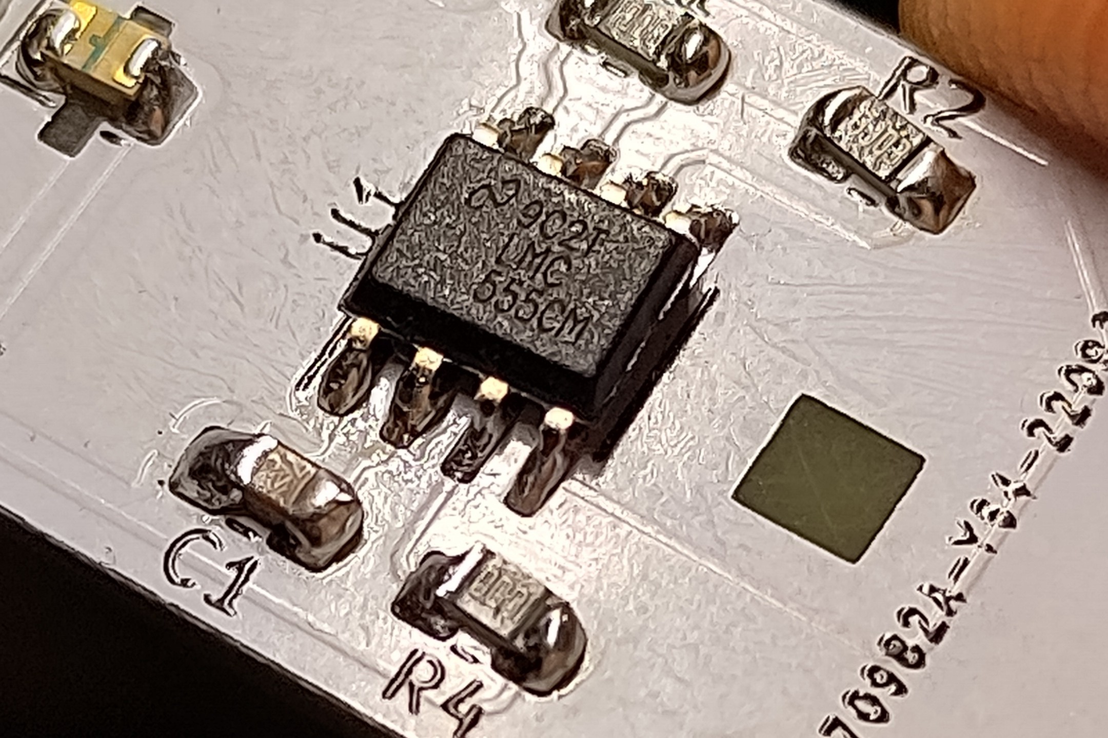
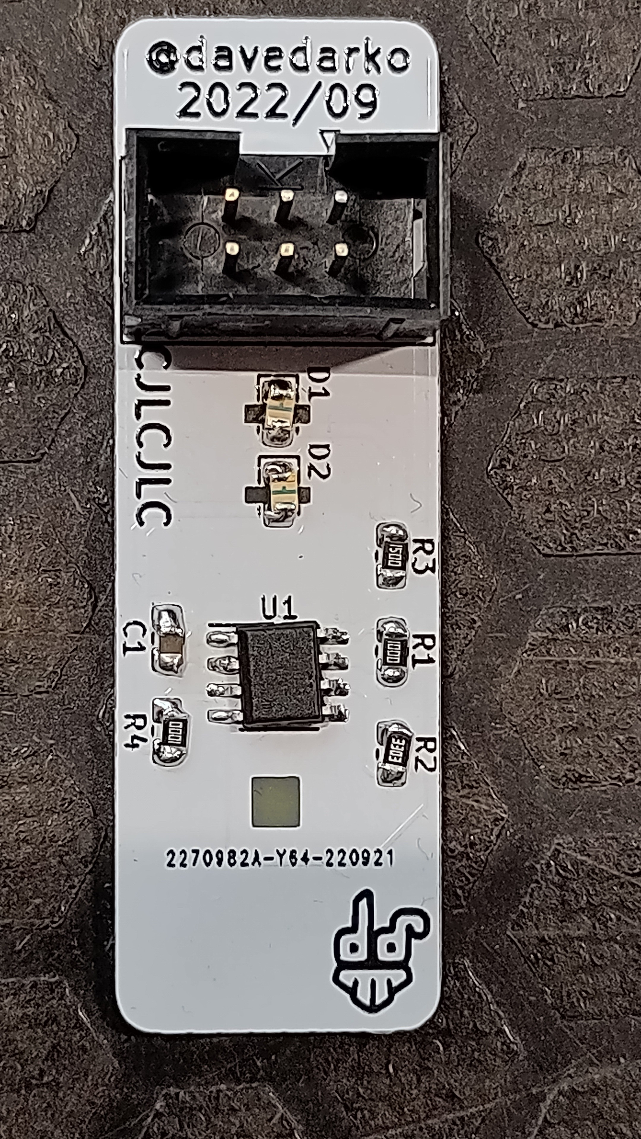
The 555 timer has a chamfer to indicate the side of thr first pin.
| 2026 | 2024 | 2023 | 2022 | 2021 | 2020 | 2019 | 2018 | 2017 | 2016 | 2015 | 2014 |
|---|---|---|---|---|---|---|---|---|---|---|---|
| 2 | 2 | 11 | 15 | 23 | 13 | 30 | 72 | 152 | 102 | 134 | 62 |
The 555 timer has a chamfer to indicate the side of thr first pin.
There are some "between the years" events happening in Europe that follow the spirits of the chaos communication congress that got cancelled this year. In a small venue with 400 people I gave this talk about my Dodecahedron! :) Was a fun first talk of this kind for me.
I couldn't find the picoprobe with openOCD until I flashed it with a pre compiled picoprobe.uf2 file instead of compiling it myself. If it works, it works - I guess.
found the related issue where I got the working picoprobe.uf2 got from: https://github.com/raspberrypi/openocd/issues/71
Basically pointing to this site where you can download the probe firmware:
assertion "ep->active" failed: file "~/Projects/pico/pico-sdk/lib/tinyusb/src/portable/raspberrypi/rp2040/hcd_rp2040.c", line 164, function: hw_trans_complete
This has something to do with the debug mode and you need a flag to run cmake first before compiling:
PICO_SDK_PATH=~/Projects/pico/pico-sdk cmake .. -DCMAKE_BUILD_TYPE=Release
make -j8
I have yet to find out what the difference between -j8 and -j4 means but hey, that up their worked.
link that helped: https://github.com/raspberrypi/pico-sdk/issues/649
video that helped:
Had some trouble compiling the openOCD version for the picoprobe on the M1 macbook. This is based on a thread on github and the official guides, plus some blog posts that basically copied from each other.
https://github.com/raspberrypi/openocd/issues/7
#install additional brew libraries
brew install libtool automake texinfo wget gcc pkg-config libusb

# some path magic so compilers know where to look for stuff
export PATH="$(brew --prefix)/opt/texinfo/bin:$PATH"

# download openocd files with picoprobe branch
git clone https://github.com/raspberrypi/openocd.git \
  --branch picoprobe --depth=1

cd openocd
./bootstrap

# this enables the picoprobe and deactivates other modules that fail to compile otherwise
CAPSTONE_CFLAGS="-I$(brew --prefix)/include" \
  ./configure --prefix="$(brew --prefix)"  \
  --enable-picoprobe --disable-presto --disable-werror --disable-openjtag

make -j4

# this will probably overwrite your current installation
# and will break openjtag
make install

# optionally remove the installation folder
cd ~/git
rm -rf openocd
twitter back log from 2020-10-24
"Time flies when you're trying to have fun with a two year old project. This is my take on an ISP for AVR and Attiny chips, than can power the target with 3V, 5V or translate to the target's voltage. I always wondered why the old version was sometimes shorting out and now I know.
The version before had POGO pins soldered directly to the pads (yes, they were mirrored for that). They were replaced with a "standard" 6 pin socket and this works fine. I was able to program plenty of targets with the new programmer. They just would not start.
With the POGO pins I never noticed that, because as soon as I was done programming with it, the target was powered on it's own and started fine. But now the reset line was held LOW because the reset pin turned into an INPUT.
The level-shifter I'm using is not bidirectional, but the direction of communication can be selected. So I lifted the pins and rewrote the USBASP firmware to change the direction whenever the red LED turns on and off (basically). Now nothing works anymore and I'm asking myself:
Should I change the schematics and find a bi-directional tri-state level-shifter? Or should I scope it and see if it's fixable with some delays?"
It seems to just work with the 5V circuitry and boots normally. Maybe it's behaving weird when it's 3.3V on the receiving side. Hm nope, also works with 3.3V. Maybe it was the target then, need to remember what I wanted to program back then.
Did some more "perfect scenario" calculations for the possible frame rates, after failing math hard at supercon, thinking that I am sending out half a million bytes for a frame on the cube.
So we have 12 * 192 * 9 bits to fly over of raw data, not including addressing and setting PWM page. At a 400kHz clock speed or 400000 bits/s we arrive at a hypothetical 19.3 fps.
What did I change to get here? After sending the data for the LEDs in bursts, I arrived at roughly 10fps and hooked the cube up to the oscilloscope to see what's going on. Turned out the clock was at roughly 200kHz instead of the expected 400kHz o.o

This might look very obvious at first sight to some, but the spikes aren't supposed to look like this and there is this magical thing that you can add to I2C lines, when it looks like that - I forgot about pull-up resistors! To allow for a fast rise you need resistors connected to VCC to help rise the potential of the capacitive natured data and clock line. To be honest I have no idea how to better explain this, but I hope the image helps a bit.
I've added 2.2k resistors to the module and suddenly arrived at 16fps! I might be able to go even faster with a different controller, but I still like the XIAO NRF52840 sense too much with all its features that I have yet to use :D
I've spent 3 hours hunting down the speed settings for I2C on the Seeed XIAO NRF sense board in Arduino, but couldn't find it. My goal was to have a frequency of 1MHz for I2C instead of 100kHz, but so far there was no chance.
it's quite frustrating that I still have no idea where the seeed library based on mbed for the XIAO NRF sense defines how the I2C works with the wire library in Arduino. I found so many registers and values where I was "aha! That's the two wire interface speed value that I was looking for!" but then nothing changed when I edited the sdk_config.h file.
The other thing that slows down the animations is the code for writing to the LEDs. Looks like the code first writes a select page and then writes a single byte for the LED pwm value. There's definitely optimisation possible in streaming plenty bytes after selecting a page, instead of ping pong-ing that often to effectively set one byte.
managed to send complete frames to the I2C controllers and now reach 10 frames per second on the NRF52840 board. After some datasheet reading I'm not so sure I can easily reconfigure the I2C to go 1MHz on the NRF52 and ordered an ESP32-S2 QT PY board to play around with. Last hope for the NRF52 is using the adafruit board libraries instead of the XIAO mbed library as I am fairly certain I saw code there that makes more sense. Would be nice to be able to use the NRF board with all its sensors (mic+accelerometer) on board.
FLASHING LIGHTS WARNING
Note to self, the distance between the SAO headers on my first oshpark penghicorn badge is 4.1inches (rounded) or 104.177366mm according to eagle file imported to kicad. Not sure I will make something with that.
# download mps compilers
brew tap tgtakaoka/mspgcc

# prepare folders

sudo mkdir /opt/homebrew/lib/msp430 /opt/homebrew/lib/msp430/lib /opt/homebrew/include/msp430 /opt/homebrew/include/msp430/include
sudo chown -R $(whoami) /opt/homebrew/lib/msp430 /opt/homebrew/lib/msp430/lib /opt/homebrew/include/msp430 /opt/homebrew/include/msp430/include

# run install
brew install libc-msp430 gdb-msp430
https://exfil.co/2016/02/11/goodfet-on-os-x/
Found a good starting point to talk with the MSP430, but sadly it runs into a weird bootloader password issue.
goodfet.bsl -P ./goodfet.hex --fromweb
Use -h for help
Use --fromweb to upgrade a GoodFET.
MSP430 Bootstrap Loader Version: 1.39-goodfet-8
Invoking BSL...
Transmit password ...
Use -h for help
Use --fromweb to upgrade a GoodFET.
MSP430 Bootstrap Loader Version: 1.39-goodfet-8
Invoking BSL...
Transmit password ...
Traceback (most recent call last):
  File "/usr/local/bin/goodfet.bsl", line 1987, in
    main(0);
  File "/usr/local/bin/goodfet.bsl", line 1887, in main
    bsl.actionStartBSL()
  File "/usr/local/bin/goodfet.bsl", line 1166, in actionStartBSL
    self.txPasswd(self.passwd)                  #transmit password
  File "/usr/local/bin/goodfet.bsl", line 1136, in txPasswd
    wait=wait)           #if wait is 1, try to sync forever
  File "/usr/local/bin/goodfet.bsl", line 801, in bslTxRx
    rxFrame = self.comTxRx(cmd, dataOut, len(dataOut))  #Send frame
  File "/usr/local/bin/goodfet.bsl", line 480, in comTxRx
    rxHeader, rxNum = self.comRxHeader()        #receive header
  File "/usr/local/bin/goodfet.bsl", line 386, in comRxHeader
    if not hdr: raise BSLException("Timeout")
__main__.BSLException: Timeout
aha! So the tutorial uses a capital P where the flag should be a small p. Or not, maybe the password stuff is set somewhere else or while compiling. writing the ./prebuilt firmware worked.
board=goodfet42 goodfet.bsl -p goodfet.hex
Well that wasn't really a solution, but somehow I got it to except the firmware, probably by using the "fromweb" flag for it, where it wasn't confused by all that.
Sure, I could try and do the same hard work that plenty people have done before me, do miserably and fail - or I could just try and get stuff from back then working. So within chip shortage I tried to get hold of the MSP chip that's featured on the GoodFET, a DIY JTAG and more probe, that isn't obtainable anywhere. Thankfully everything I needed was accessible and so I started redesigning the GoodFET in KiCad, swapped some parts and added rounded corners basically and ordered the boards at OSHpark. Why did I do that? Because all the tutorials from 2010 basically start with "connect your GoodFET to the im-me messenger" and well I need one then, of course.

Had to share this beauty

R2-D2 has some fancy lights in his head, but here with the 40% scale they resulted to holographic stickers instead. I might change that with some fibre optics (lichtleiter for ebay) or replace it with an OLED - not sure yet! both displays come together to 225 LEDs.
LED system:
R2-D2 seems to run on 3 voltages:
From other projects I've learned about drone parts, known as BECs that convert LiPo voltages to 5V and most often 12V. I want to modify the HTPDB-XT60 module so it will convert to 5V and 6V instead, so I can use a 2-cell LiPo pack.
To control the motors I will use a DRV8838 single motor driver for the dome and a DRV8833 dual driver for the leg wheels
This thing is packed with interesting stuff!
Dome
Body
Lot's of older projects I designed in Eagle, but I'm not using that anymore. Recently I found some cool jars and wanted to make a new bulb, but had no idea what the correct arrangement of LEDs was. So here are screenshots of the schematics to work with, done on my old computer.

