Sometimes you just want that special extra protection for your future projects (or dreams of them) or maybe you need a nice purpose for those old or faulty boards that are cluttering your drawers - if so - I might have a solution for you:
a totem of failure
2016-12-31 15:40:47
Recycled LiPo Powerbank / PSU | link drop
2016-12-30 17:16:54
http://lygte-info.dk/info/USBinfo UK.html
Game Boy Cartridge plus Programmer | The most expensive RGB light
2016-12-22 17:25:16
;)

:3
2016-12-22 11:23:24
So I never said that this was in ONE envelope (actually two that arrived the same day) and it's what will haunt me for the next weeks to come ;)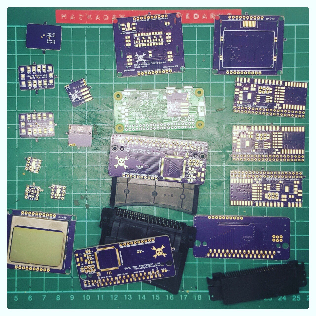
That's a first
2016-12-13 13:04:01
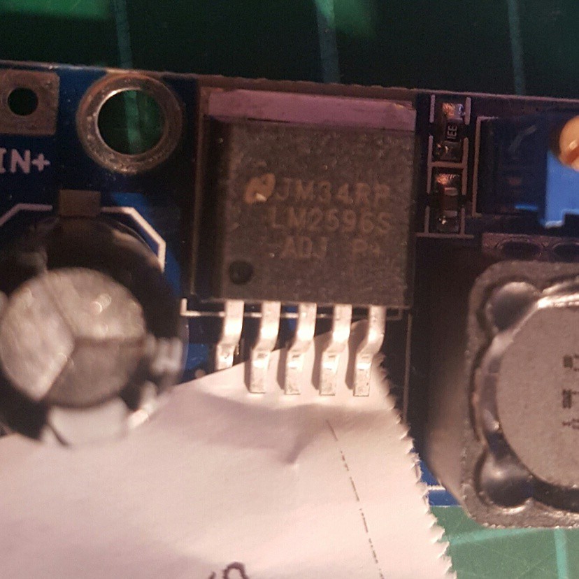
First OTA step-down power converter :D
tools I really want to make / have
2016-12-10 11:20:38
Starting this list to remind me that I want tools like this and that they should be fairly easy to make.
pressured air thing
to blow away dirt and dust
tiny vacuum chamber
for getting out the bubbles in 2K epoxy covered things
shaker
for shaking solvents like ABS + Acetone
vibration mini table
bubbles / shaking / etching you name it
I guess I just can't stop buying stuff
2016-12-07 11:32:44
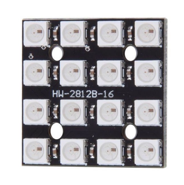
So why did I buy this? It just reminds me of this websites logo, so why not turn it into a badge or combine it with an ESP8266 and write a little notifier for skulls (or likes) on projects. I still wan't to play around with the API of hackaday.io some more.
USB cable tester | Board 2 is running
2016-12-06 09:16:47
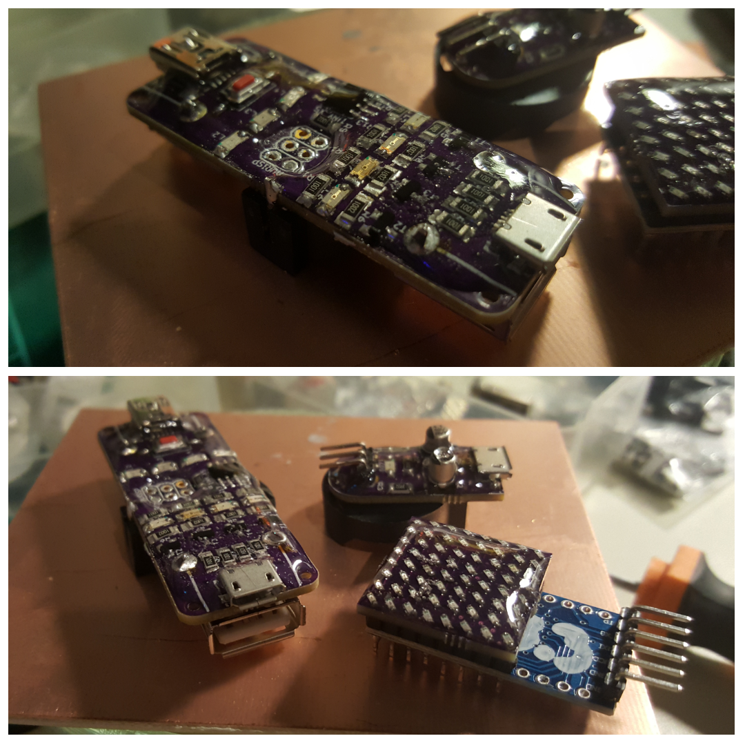
Since the USB micro connector broke off of the first board I had to solder one again. Still have to check if the consumption still is that low and all the code really works as intended.
Also - Resin / 2K epoxy!
USB cable tester | uh wait, that fits the 1kB contest
2016-12-04 14:08:36
noice! It compiles with arduino! https://hackaday.io/project/6858-usb-cable-tester/log/24876-verify-your-results
I will test the circuit when I get home! I'm glad I just went through my projects list and that there's a USB port broken. yeah!
Schlachtplan ToDo
2016-12-04 14:02:11
#Heimdall - dumb remote home
There are already two or three lists I've put and ignore here, but I don't care. I just went through all my projects to see what I might have neglected for long enough now and sometimes I just forget what I was up to, merging ideas and project is also a good thing to not get too crazy about losing / forgetting / neglecting stuff, so here's my ToDo.
- make a prototype to earn some of those skulls
- maybe with the Nokia LCD thing
- change rgb colors when showing different stats
- finish the pcbs for dirtypcbs.com (sorry OSHpark)
- make a 3D case for the backside (finally), at least close the back side
- add buttons for setting the time
- make a case / laser cut template
- maybe order some more boards
- Projects:
- Light switch remote for MQTT stuff
#Locomatrix - 3D POV - a different approach
- make it work :D
#Heimdall - dumb remote home
- add alexa support
- add neo pixel ring
- manage USB cable wiring
- gracefully shutdown PI zeros with PI3
- add camera (maybe with servo(s)?)
- add fan control
- wait for board and solder it
- make an image that works
- watch some more Doctor Who and finish a working thingy
#Johnny IV #R8-D8 - a distant relative of R2-D2 #NRF24L01 remote project
- make it work
- control R8 / Johnny IV with NRF24L01 remote project
- add base station
- <s>make another one because the micro USB plug broke off</s>
- maybe 1kB contest it / fit on attiny13A
- attinyfi it
- oh boy, have to finish that
- paint it
- make a clip for the battery
- fix the wiring of the LEDs
- write a better sound library
- solder the two boards with hot air station
- finish program on attiny85, then strip down to fit in 1kb
- write software to make it show next public transportation times etc.
Commodore 64 C64
- get the SID chip running making sweet sounds
Nokia 3310 / 5110 display board | there's another display in town
2016-12-01 12:24:38
https://catmacey.wordpress.com/2013/08/08/breakout-board-for-nokia-1202-lcd/
It's a Nokia 1202 display, having a whopping pixel resolution of: 96x68
where the Nokia 3310 has merely 84x48
Nokia 3310 / 5110 display board | fun with eBay
2016-11-29 19:49:56
The first display from eBay came the other day and these are the winning pictures that got me a second one send to:


No boards here yet, so it doesn't hurt. Well it does hurt seeing those monstrous scratches. Two other displays with pcbs arrived as well, no scratches and with a protecting foil.
Portable Raspberry PI Zero | changing pins works!
2016-11-27 22:06:35
I've mapped pin12 and pin13 to play audio! woot.
The following code is not mine and taken from:
https://www.raspberrypi.org/forums/viewtopic.php?f=44&t=39138
I just want to have everything in one place and have a copy of it somewhere.
/*
Utility to switch Raspberry-Pi GPIO pin functions
Tim Giles 01/04/2013

Usage:
$ gpio_alt -p PIN_NUMBER -f ALT_NUMBER

Based on RPi code from Dom and Gert, 15-Feb-2013,
and Gnu getopt() example
*/

#include <ctype.h>
#include <stdio.h>
#include <stdlib.h>
#include <unistd.h>
#include <fcntl.h>
#include <sys/mman.h>

#define BCM2708_PERI_BASE        0x20000000
#define GPIO_BASE                (BCM2708_PERI_BASE + 0x200000) /* GPIO controller */
#define PAGE_SIZE (4*1024)
#define BLOCK_SIZE (4*1024)

int  mem_fd;
void *gpio_map;
volatile unsigned *gpio;
void setup_io();

// GPIO setup macros. Always use INP_GPIO(x) before using OUT_GPIO(x) or SET_GPIO_ALT(x,y)
#define INP_GPIO(g) *(gpio+((g)/10)) &= ~(7<<(((g)%10)*3))
#define OUT_GPIO(g) *(gpio+((g)/10)) |=  (1<<(((g)%10)*3))
#define SET_GPIO_ALT(g,a) *(gpio+(((g)/10))) |= (((a)<=3?(a)+4:(a)==4?3:2)<<(((g)%10)*3))

#define GPIO_SET *(gpio+7)  // sets   bits which are 1 ignores bits which are 0
#define GPIO_CLR *(gpio+10) // clears bits which are 1 ignores bits which are 0


int main (int argc, char **argv) {
  int opt, flag, n_pin, n_alt;
  flag=0;

  while ((opt = getopt (argc, argv, "hp:f:")) != -1) {
    switch (opt) {
    case 'h':
      break;
    case 'p':
      n_pin = atoi(optarg); flag |= 0b0001; break;
    case 'f':
      n_alt = atoi(optarg); flag |= 0b0010; break;
    case '?':
      // getopt() prints error messages, so don't need to repeat them here
      return 1;
    default:
      abort ();
    }
  }

  if (flag != 0b0011) {
    fprintf (stderr, "Usage:\n$ gpio_alt -p PIN_NUM -f FUNC_NUM\n");
    return 1;
  }

  setup_io(); // Set up gpi pointer for direct register access
  INP_GPIO(n_pin);  // Always use INP_GPIO(x) before using SET_GPIO_ALT(x,y)
  SET_GPIO_ALT(n_pin, n_alt);

  printf("Set pin %i to alternative-function %i\n", n_pin, n_alt);

  return 0;
}


void setup_io() {
   /* open /dev/mem */
   if ((mem_fd = open("/dev/mem", O_RDWR|O_SYNC) ) < 0) {
      printf("can't open /dev/mem \n");
      exit(-1);
   }

   /* mmap GPIO */
   gpio_map = mmap(
      NULL,             //Any adddress in our space will do
      BLOCK_SIZE,       //Map length
      PROT_READ|PROT_WRITE,// Enable reading & writting to mapped memory
      MAP_SHARED,       //Shared with other processes
      mem_fd,           //File to map
      GPIO_BASE         //Offset to GPIO peripheral
   );

   close(mem_fd); //No need to keep mem_fd open after mmap

   if (gpio_map == MAP_FAILED) {
      printf("mmap error %d\n", (int)gpio_map);//errno also set!
      exit(-1);
   }

   // Always use volatile pointer!
   gpio = (volatile unsigned *)gpio_map;
}
One time setup:
gcc -o gpio_alt gpio_alt.c
sudo chown root:root gpio_alt
sudo chmod u+s gpio_alt
sudo mv gpio_alt /usr/local/bin/
Cron that:
gpio_alt -p 13 -f 0
gpio_alt -p 12 -f 0
DC motor board with attiny13 | Blinking and interrupts and stuff
2016-11-27 10:41:49
When I started with the pin setting I first confused the pin direction setting byte with the state setting byte :D So I thought of breaking my code in peaces to fix the problems and start with the basics.
I found a library for the Attiny13A written by MCUdude on github - link is in the link section - that gives me a head start to use the Arduino IDE for coding. Feels weird saying that. Here's code for an LED flasher (german: "Wechselblinker") - two leds alternating the blinks.
void setup() {
  // put your setup code here, to run once:
    DDRB = 0x03; //PORTB
}

void loop() {
  // put your main code here, to run repeatedly:
  PORTB = (1<<PB1) | (0<<PB0);
  delay( 1000);
  PORTB = (0<<PB1) | (1<<PB0);
  delay( 1000);
}
I'll post the other code later.
Heimdall - dumb remote home | PCM1863 board soldered
2016-11-25 22:23:11
TSSOP30 boards I had to design are here! Not sure when I will have the chance to play with them though.

DC motor board with attiny13 | 1kB challenge
2016-11-25 22:11:07
I thought it would make sense to send this project in for the challenge, since it's basically a servo without the feedback of the resistor.
First I need to solder some wires to the pins, Rev1 will definitely have some SPI headers on the bottom to program the attinys. Or I will have to tinker up something.
Not sure how the attiny13s will behave, they arrived today and I only thought "ah well, what the heck" and went on with it.

Game Boy Cartridge plus Programmer | boards ordered
2016-11-24 17:07:55
The LCD display board and the Socket board are both ordered, as well as a tiny QFN Attiny85 board.


All boards were upgraded to be send with "super swift" - so I'm looking forward to a 5x3 boards delivery :) :) :)


yo - @Stefan-Xp - here's a picture of the socket and the super game boy it's from:

Portable Raspberry PI Zero | boards ordered
2016-11-24 17:04:32
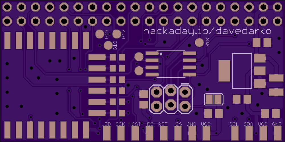
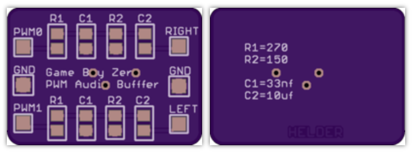
There is currently no sound on this board, but I've ordered this anyway with some testpoints for the possible sound pins and an extra board you can check out below (not designed by me but someone who builds raspberry pi portables). The attiny85 is connected to the PI via I2C and the TFT LED output of the driver - think basic on/off via driver and pwm via i2c. It's a decent prototyping board to get along, I think.
Gameboy Zero PWM Audio SMD - by Helder
https://oshpark.com/shared_projects/qUEOjE0n
Portable Raspberry PI Zero | party on!
2016-11-19 21:53:02
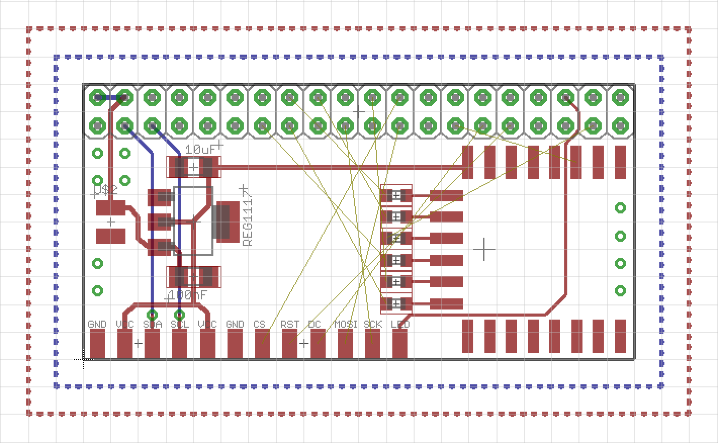
soo, still not validated, but I'm happy to give it a try as soon as possible - a breakout board to connect the Raspberry PI with the TFT display, wi-fi and I2C and stuff. I'm tired.
Fixietube - Fake Nixie Tube displays | getting interwebs time
2016-11-18 19:27:03
http://embedded-lab.com/blog/making-a-simple-esp8266-internet-clock/