zynthia - sequencer synthesizer | more expansion ideas
2020-02-24 15:18:05
I was watching a review of a modern sequencer and saw it going back and forwards. Thought to myself I could maybe connect the "overflow" pin of the 4029 and the forwards / backwards selection with a 4017 / 4022 chip. Need to investigate that :D
Club Matrix | Not The Final Countdown
2020-02-17 11:55:42
We had an event with short talks at the xHain Hackerspace recently and we wanted to use the club matrix as a timer for the presenter. I have yet to write a font generator and a script to do that though and the only thing I can kind of reliably do is playing a video. The sane solution: search on youtube for a 15min countdown video, which kind of worked.
But since we were at the hackerspace, one member wanted to try to let ffmpeg generate the countdown. The first version of the script by Niklas was almost perfect, but used a PNG as a background image. Then another member (danimo) took a look and removed the background image and let ffmpeg turn the background from green to red in the last minute.
After activation of linear advance with .4 nozzle:
M900
Advance K=0.50
looking back to 2019 and forward to 2020
2020-01-05 19:01:48
2019 Bigger Projects
#Club Matrix Array of 10 8x8 WS2812B LED matrices, controlled by a Raspberry PI through a DMA library. Images can be send as UDP packages to the matrix, if you happen to know the IP address.
SX-64 inspired Raspberry PI case Inspired by portable computers from the 80ies, I started to build a case around a Raspberry PI with 10mm extrusion profiles and lasercut panels to mount stuff to. https://www.youtube.com/watch?v=vXGr7-_U_tY
#400 LED XY oscilloscope For another video done for "elemen14presents", I cobbled together schematics out of Forrest Mims III's engineers notebook to make an LED oscilloscope that has 20 x 20 10mm LEDs.
#LED handheld This monster pixel game uses some tricks like charlieplexing, soldering LEDs upside-down to shine through the PCBs and hours of sanding on a 3D printed case.
plenty other projects for element14presents Here's a list of all my appearances as a video host for element14presents, plus some extra episodes of livestreams of the makercast - podcast that me and some other youtubers started. https://www.youtube.com/playlist?list=PLN5aOBKmcf5-954RyDwuX6KYXCDLIr4BO
zynthia - sequencer synthesizer | New DIP version
2020-01-03 20:34:12
I've been asked for a DIP version and this is basically the latest SMD version with swapped parts and a bigger PCB. Ordered at JLCPCB in red.
ToDo:
check if C2 needs to be a 10th of current value
Club Matrix | Showing the IP on startup
2019-12-27 15:16:12
Here at 36C3 congress the "bla.local" bonjour stuff doesn't work. Incase you see 127.0.1.1 as the IP, you have to edit that out in the following file:
sudo nano /etc/hosts
Club Matrix | From 10 x 8x8 LEDs to 40 x 16 LEDs
2019-12-24 19:30:18
So this took me a while. The library that I'm using stores the matrix data in a one dimensional array with the length of 40 * 16.
Each LED matrix is 8x8 and are connected in that order:
When I finally found the error in this function, I had already written a lookup table for all the 640 LEDs. This is fixed for my setup, but it should be possible to rearrange it for others.
int matrix_arrangement[] = { 0,1,2,3,4,9,8,7,6,5 };
voidclub_matrix_render(void)
{
for (int i=0; i<led_count; i++)
{
int led_real_x = i % width; // 0 to 39int led_real_y = i / width; // 0 to 1int matrix_number_x = led_real_x / 8; // should be 0 to 4int matrix_number_y = led_real_y / 8; // should be 0 or 1int matrix_number = matrix_number_y * 5 + matrix_number_x; // 0 to 9int matrix_x = led_real_x % 8; // 0 to 7int matrix_y = led_real_y % 8; // 0 to 7
ledstring.channel[0].leds[matrix_arrangement[matrix_number] * 64 + matrix_y * 8 + matrix_x] = matrix[i];
}
}
WIFI Game Boy Cartridge | Soldered a prototype, found a bug
2019-12-14 14:58:34
Finally decided on soldering a PCB and when I programmed it, it wouldn't start the program afterwards. So I was calling for help on twitter and got some well meant advices about pulling certain pins that no ESP32 dev board pulled up. It took me a while to notice that I was missing the capacitor in my reset circuit. I didn't check what C6 actually does while debugging, so I thought being so close to the ESP reset pin and resistor, that it was part of it. With a bodged on capacitor it now resets to run the program!
So far it's only a cartridge shaped ESP dev board that can talk to 5V devices, but it's good to know this is programmable!
LED handheld | Firmware
2019-11-27 20:54:22
Getting stuff done when you're watching your niece and changing diapers isn't an optimal combination! But I managed to write a little library that handles the display driving etc. So now I have to reprogram everything I had running before, like the enemies that are moving and drawing to the frame that then get's shown.
Do or Donut SAO | check stock before deciding on parts
2019-11-27 20:45:04
The title says it pretty much, but I had some trouble getting somewhat reasonable priced IS31FL3731 in SSO, while you can get the QFN version just anywhere. My current BOM for one donut is around 7 Euros now, which still seems reasonable. 800 LEDs in 0603 are coming my way, too. Hundreds of red, yellow, orange, green, blue, white, pink and purple.
SX-64 inspired Raspberry PI 4 thing
2019-11-26 16:50:59
So I've made this thing for element14 presents, never really had a set and forget PI to work on. I do like the optics of the SX-64 very much and all the other "portables" from the 80ies. I went with makerbeams 10x10mm aluminium extrusions for the frame and some lasercut MDF to hold everything together. Still needs an enclosure, but I'm pretty happy with it.
I tried to make the 2K display work, but it was too flickery and I couldn't get it to work properly, so I switched to the official display.
I've chosen to go with JLCPCB and order 5 white test boards and a bunch of LEDs.
Mr. Robot shitty addon | Amplification by using inverted oscillator output
2019-11-18 18:05:37
When I was talking with people about how some badges use two pins of the attiny, I basically explained it to myself while trying to explain to others why it would be louder. Instead of just pushing the speaker from the resting position, you also pull it back, when connecting both the inverted oscillator pins to a speaker. Now at the airport and thanks to seeing Charles Lohr at the supercon, I remembered that he actually did that. I need to further hack that bodged prototype I guess :D
Mr. Robot shitty addon | Hackaday Supercon updates
2019-11-17 20:28:37
Friday night at supercon I decided to spend some time on the I2C part of the firmware. It's pretty simple, but I'm now able to send data from the #Penghicorn badge to this SAO and it will play a tone. Of course this can be further expanded, but I'm quite happy with the beeps. The speaker is very quite though and I need to take a look at other preferably surface mount speakers. Someone made a beeping R2D2 SAO and that has a nice speaker I want to check out.
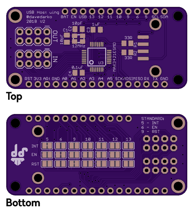
MAX3421E FeatherWing | new found motivation
2019-11-05 10:21:20
I still need to make this work / compile with all the feathers, sounds like a good software project for my vacation, right? The PCB could get got an update too, all 8 inputs and 8 outputs on a header.
zynthia - sequencer synthesizer | wiring diagram and BOM
2019-10-03 12:43:02
always wanted to do this, but it needed a tindie message to force me to finally draw this.
Cheap Chinese Closet Controller | more problems and fixes
2019-08-29 14:53:25
Two out of three solenoids are "burned" / jammed at this point. When I was cutting the switch connectors off of the locks, I didn't check the wiring. Some of the connectors had switched red and black wiring. I first thought my 700mA was not big enough, but it died regularly when two coils where powered at the same time.
Now I only have a problem where my signals aren't strong enough every 9/10 times. Two times out of those it will recognise something, but then the checksum must be bad as it doesn't do what it was told.
Not yet sure how important that is, but I found a 4k7 pulldown resistor on the A+ connection of the relay board. The 4k7 resistor connected to B- leads to nothing an unpopulated resistor footprint. The chip itself seems to be a MAX485.
Biasing and termination resistors in a story factor with oscilloscope pictures:
LAMEBOY - another ESP12 handheld | good vibrations
2019-08-22 19:50:17
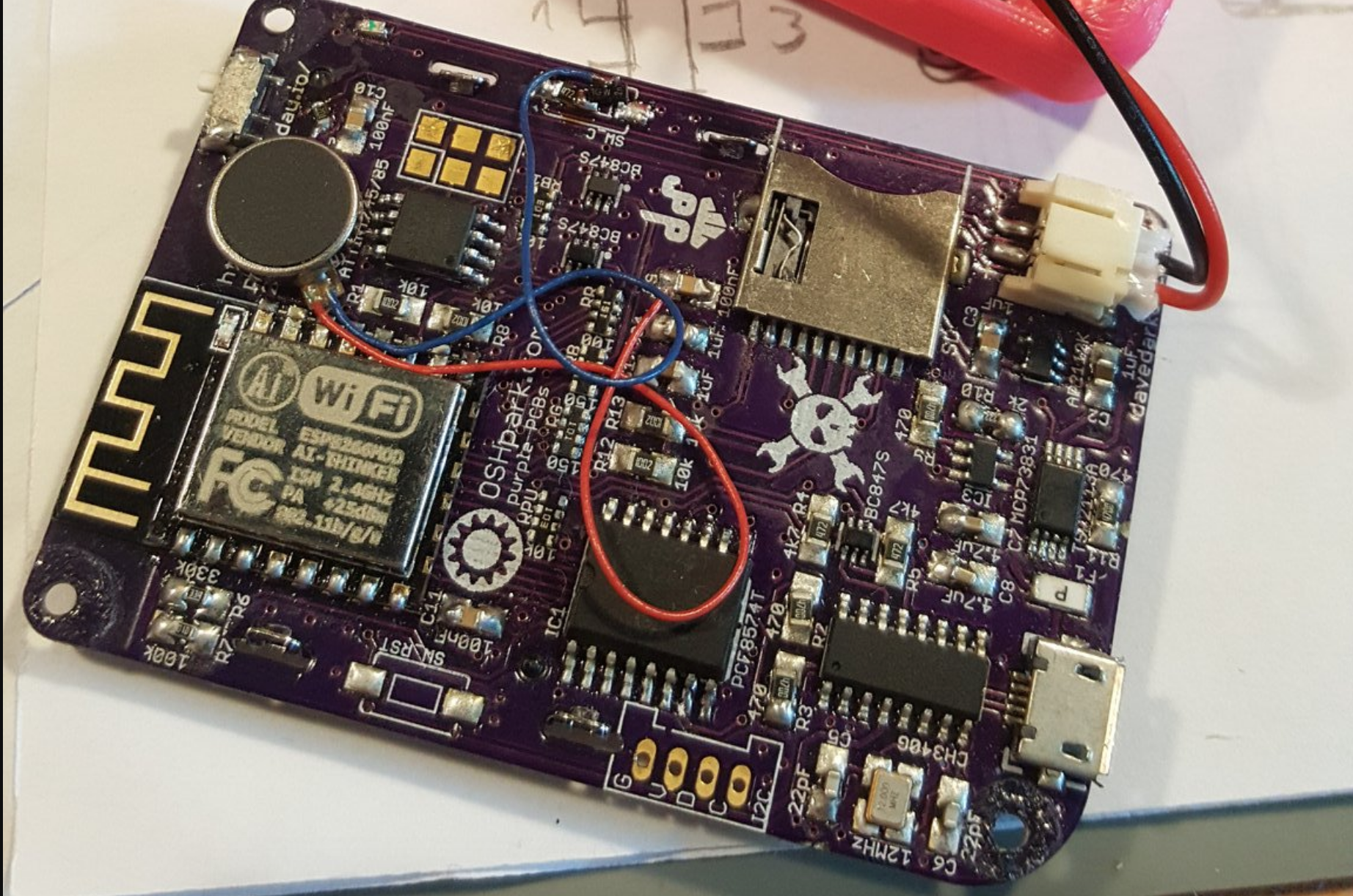
Added minimal changes overall, but they are quite a decent change functionality wise. When woody added a pager [here], I was amazed by the idea. When I saw him and his Lameboy the other day at the 3rd Hardware Happy Hour in Berlin, I decided to add that to one of my own and add an update to the schematics.
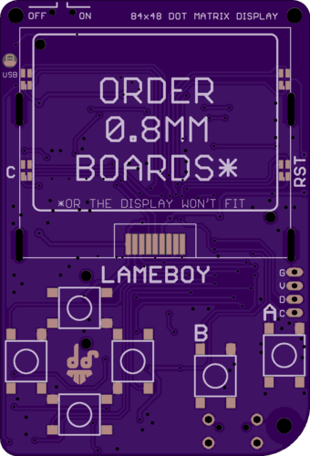
Much often I forget to add sound to my projects and here I try to free GPIO0 from resetting the LCD and instead connect a tiny buzzer to it. The LCD has a reset circuit added now.
I'm undecided to wheather I should order these versions or mod the other 10+ pcbs though, so I'll just update the github repo for now.