D1867G based keyboard hacks | Repairing the LCD of a Casio VL-Tone VL-1
2021-07-25 21:45:32
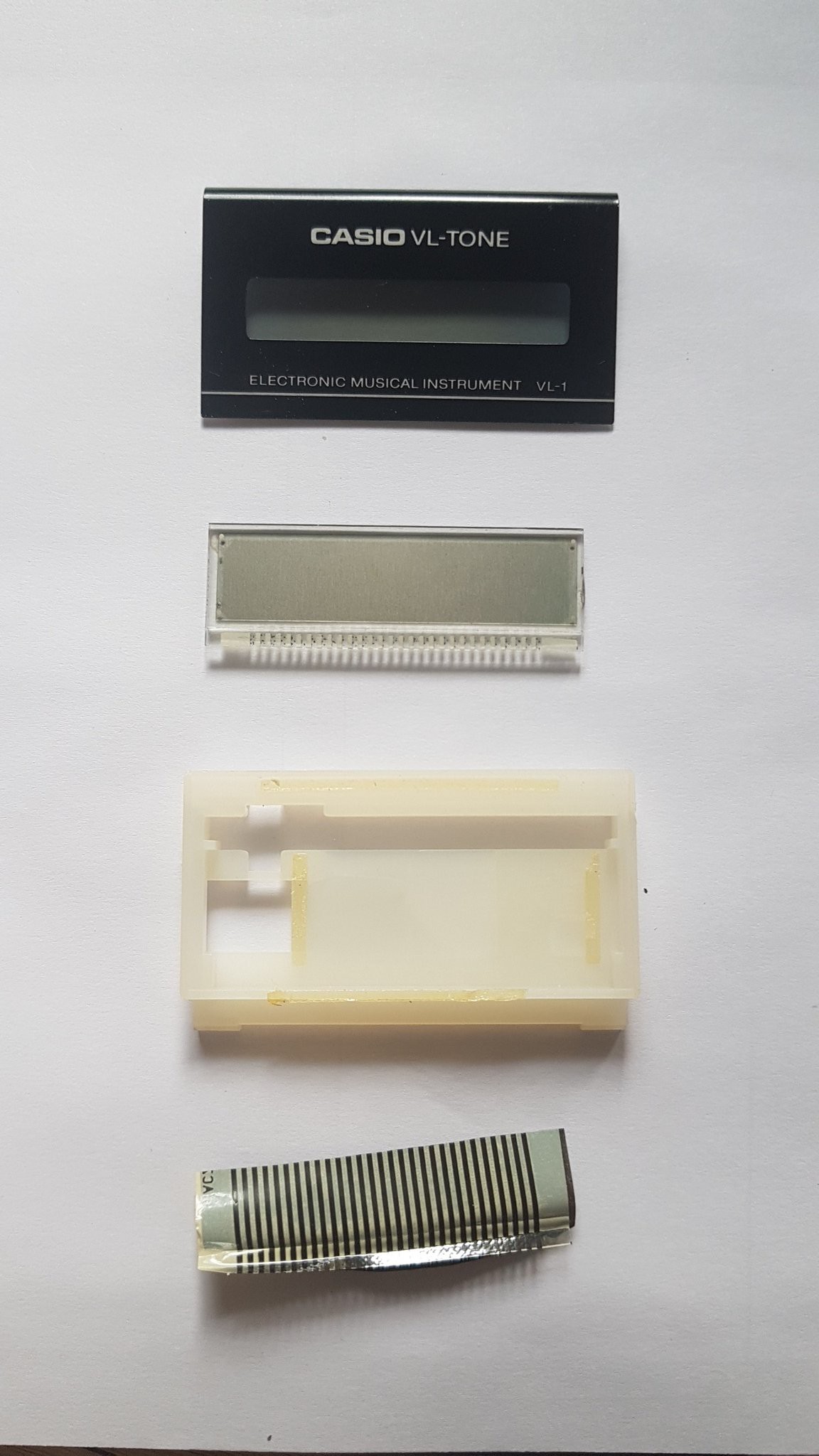
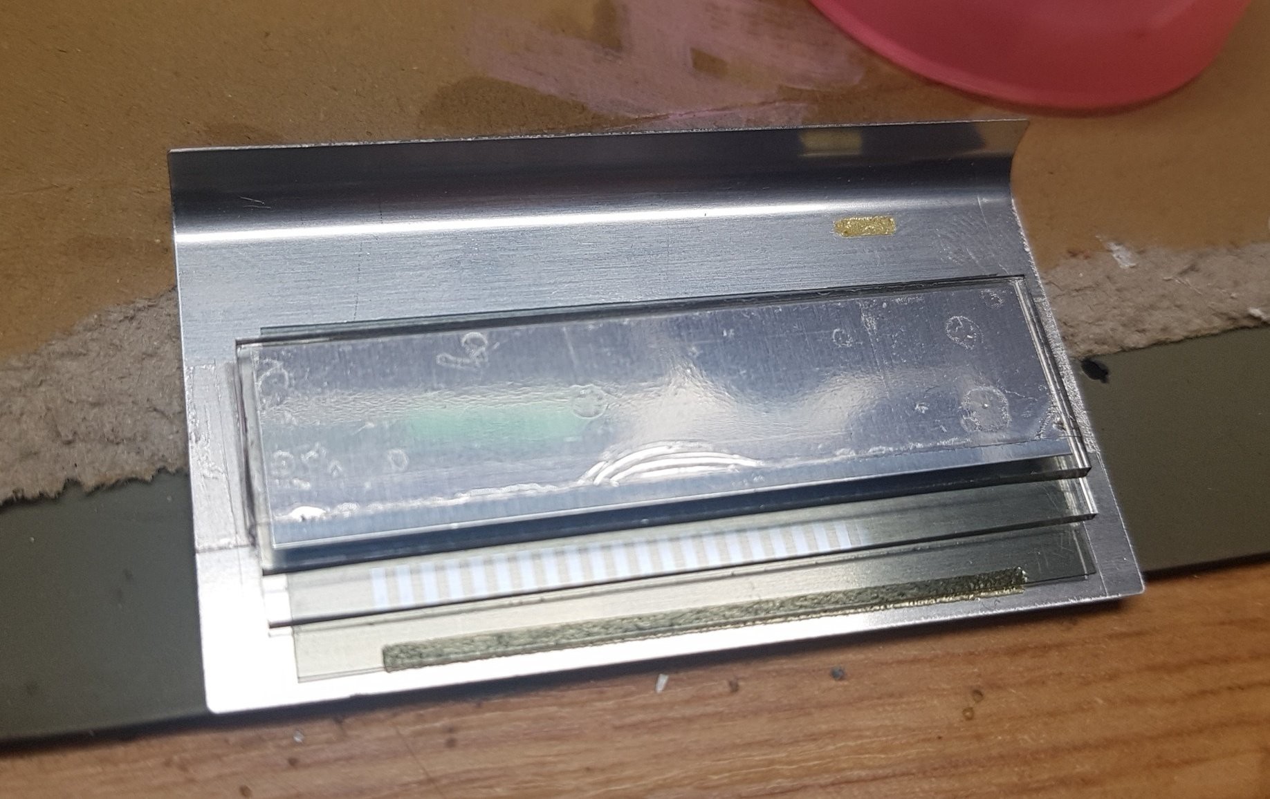
This is a super clickbaity title, since I don't have anything to show yet. But I will set my case of why I think it's doable. First off something weird that you might miss when taking it apart: the black cover has a polarising filter glued to it, which you need to see any change on the LCD. The cable that is connecting the PCB and the LCD will most likely not stick to your LCD anymore. In the picture below you can see the shadow thrown by the sticky glue that was supposed to hold the cable to the contacts on the LCD between the glue. There's a frame holding the display in place.
With a bit of help by WD-40 you can sulk the glue and later remove the residue with a q-tip. The WD-40 needs to be removed as well, best to use some alcohol I guess. In the picture below you can see the pads on glass very nicely. Now you can't solder to these pads, but you might know that zebra silicone strips exist, that only conduct in one direction.
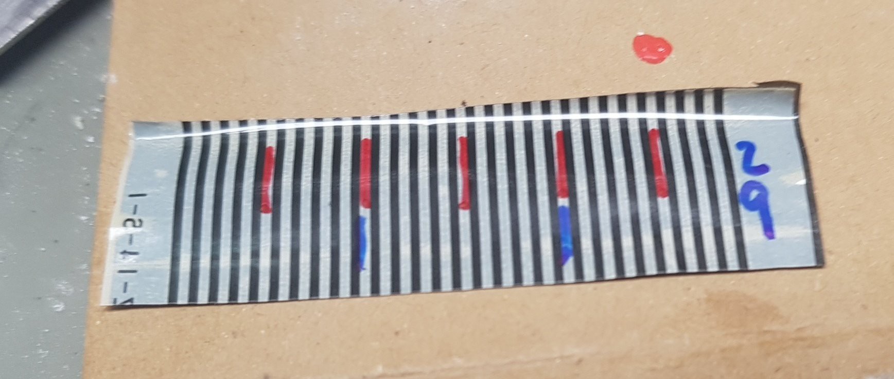
Down below you can see a piece of the cable that I've cut with some scissors. It has 29 tracks / wires and the display is grouped in segment triplets - so there are 3 x 26 = 78 segments on that LCD. - 8x 7-segments
- 8x '#' = 64
- 8x decimal point
- 5x calculator related segments
- beat indicator
Since these pins are also on any other Keyboard and there's a segment that blinks in the speed of the rhythm, this is of interest to people that want to modify their D1867G based keyboard.
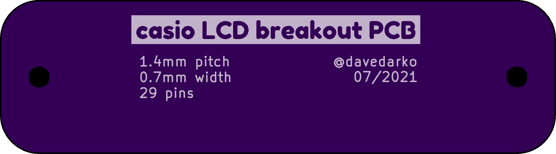
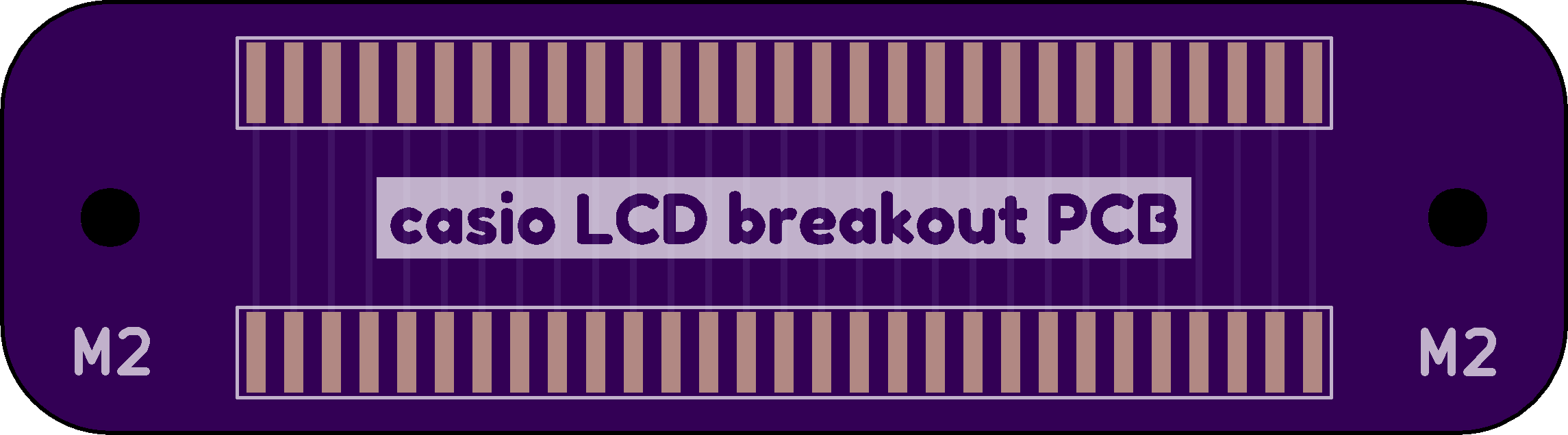
I've ordered five zebra strip with the length of 5cm for less than 10 Euros. With the right size, the help of some 3D printing and a small PCB design this should be fixable. PCB is designed and ordered.
New PCB For Calculator Watch | working in KiCad
2021-07-25 14:31:13
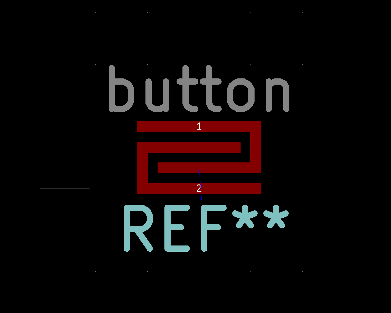
The original footprint of the keyboard buttons comes in these interlocking C-shapes. New to KiCad I wondered if it would be even possible to generate something like this. Turns out you can create custom shaped footprints like this in the footprint editor. One catch, you have to work around a standard pad and add to it. At first I was drawing the complete shape and had a 2mm x 2mm right in the center.
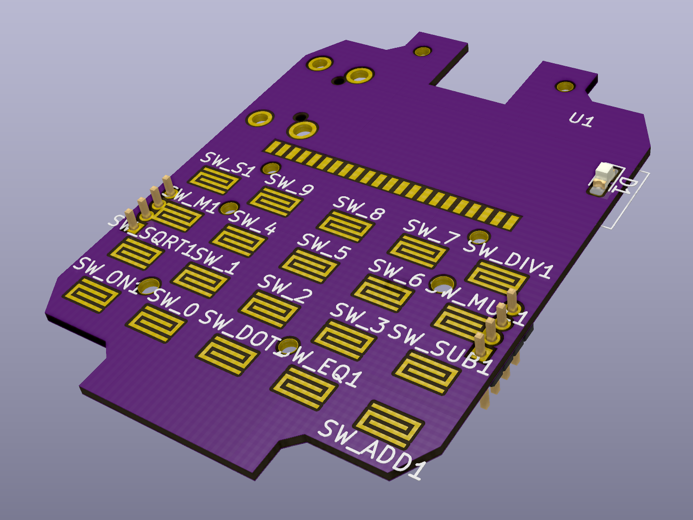
I still need to design and replace footprints here and there, but I wanted to see some renders, so I gave everything a fitting part. The USB micro-B is a storage driven choice. Since all this is open source you're free to change it to whatever plug is to your liking! There are copper bits in the drill holes, I need to fix that.
New PCB For Calculator Watch | progress on the schematic
2021-07-25 14:17:01
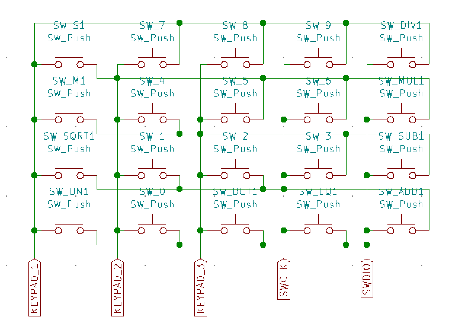
To see what's possible to add to the project, I needed a pinout list. Sadly the datasheet has a single table with all (G) 48pin, (J) 64pin and (N) 100pins in it, so that the L22G pins are all over the place. I printed out the 3 datasheet pages and cut them down and glued them together to a single page. I then marked all the LCD pins, USB and SWD pins and took a look at what was left: 10 pins. With a keyboard matrix of 4x5 pins I would normally have to use 9 pins, but instead I will use charlie-plexing to scan the keyboard. I was told that I can also use the SWD pins for other shenanigans, so I used them for the keyboard matrix and was now left with 7 more pins!
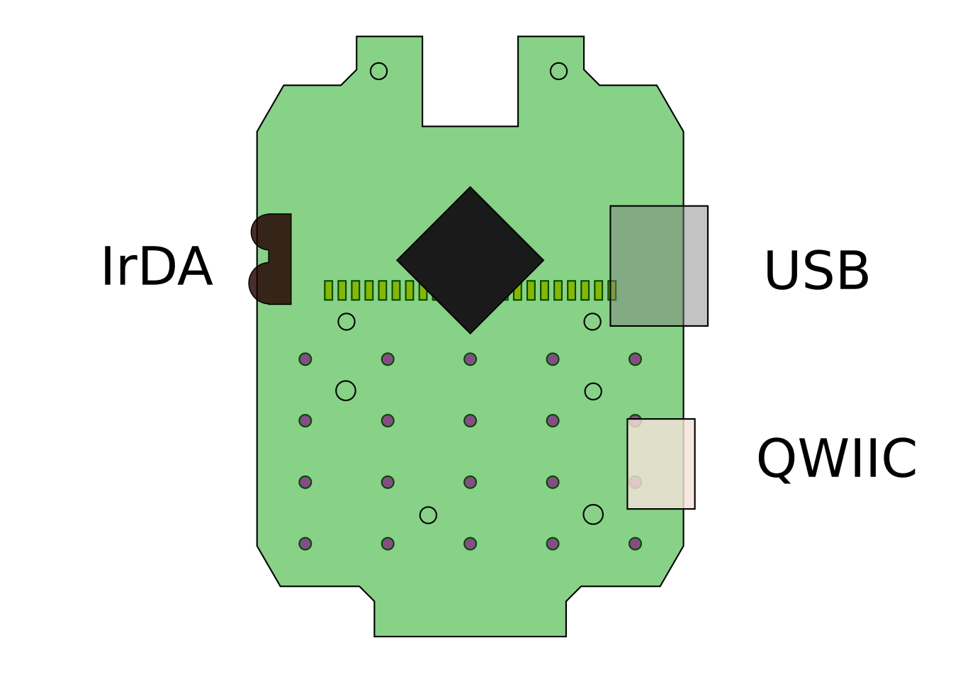
For communication I thought it would be nice to have an Infrared setup. I might be able to run tv-b-gone on it or even switch channels, ha! The TFBS4711 seems like a good tiny candidate for IR communication, so I chose that to connect to the SERCOM1 pins plus an extra pin for the shutdown pin. It might take a while until I have that functional, as there are other things that I would like to get running first.
There were two more pins of an USART interface free, so I chose SERCOM5 to be the I2C pins and connected them to a QWIIC connector. Might come in handy for controlling wearables in the future. All these addons including the USB connector mean the case needs to be modified.
That leaves us with two more pins that will be used for the piezo buzzer and the LCD backlight LED. There's a steep learning curve ahead of me when it comes to the firmware and integrating everything into the Arduino environment.
USB cable tester | New Revision
2021-07-19 00:35:03
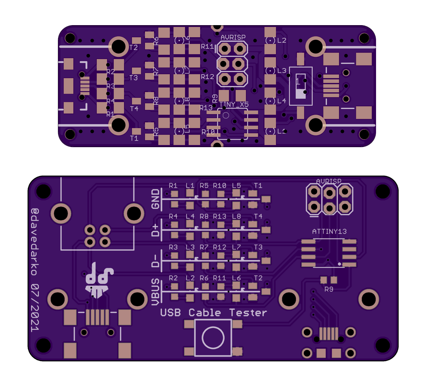
Today I went sorting through some USB cables, but before I could test anything, I had to solder the third and last of the boards that I had ordered years ago. The micro-B USB socket held for 15 cables before I had to add glue because it got loose [log for board 2]. So I decided to update some parts on the PCB and shift things around.
USB-A + micro/mini Sockets are turned 90 degrees, so you can test shorter cables
additional USB-B connector so you can test A-B cables
button is now a 6mm x 6mm sized one
LEDs all point in the same direction and are marked, good for soldering
changed micro-B footprint for something with 4 prongs
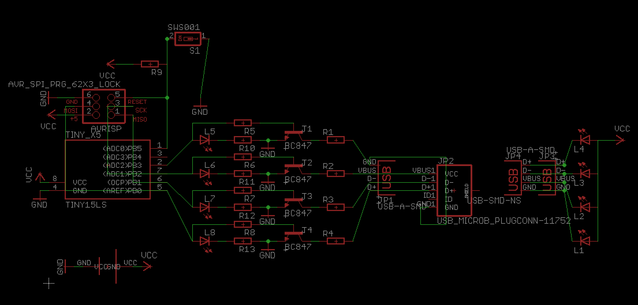
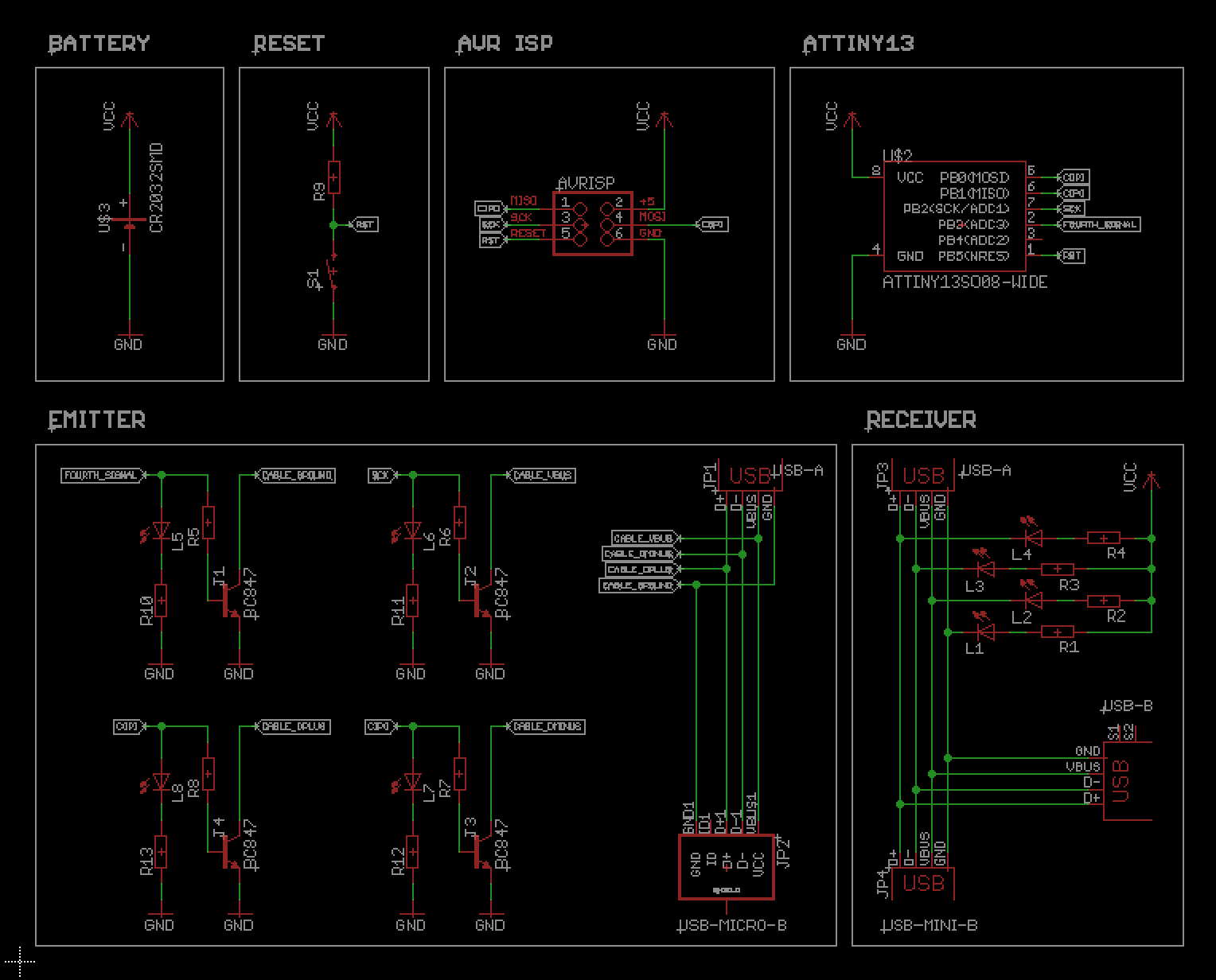
Check out this old space ship of a schematic:
And here is the (hopefully improved) new schematics, I think it's more readible, but not everyone is a fan of too many labels.
There's still one pin left on the Attiny, anyone any ideas for it?
New PCB For Calculator Watch | ATSAML22 | hardware choices
2021-07-18 10:51:03
There are different versions of the ATSAML22, for this purpose I have set my eyes on the ATSAML22G18A, it has the lowest pin count, meaning it's the smallest, while also having 256kB SRAM for programs. The amount of SRAM is probably not necessary in the end, but for developing it is good to know that you have enough space and can downgrade to reduce BOM cost. The chip has an integrated LCD controller with lots of options and 23 dedicated pins that are highly configurable - perfect amount for the 22pins of the watch LCD.
Another way of controlling the LCD could have been using the very well supported Holtek HT1621 and a controller of your choice, like maybe an ESP32 or a nordic chip. An Integrated LCD controller can also be found in the Atmega169, but it's an EoL product and the datasheet from 2006 says "Not recommended in new designs".
D1867G based keyboard hacks | need to work on the pinout of the chip
2021-07-17 22:40:23
here's a good starting point in form of a video
New PCB For Calculator Watch | PCB dimensions
2021-07-17 20:57:46
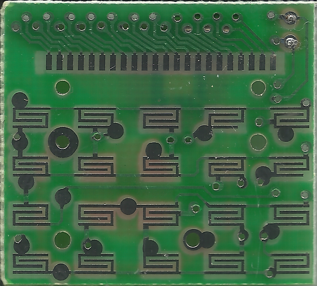
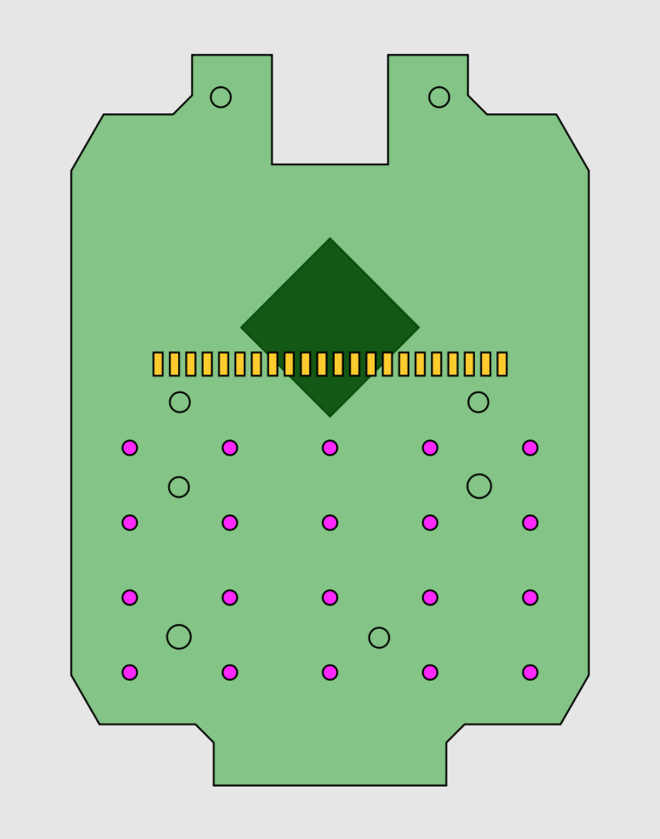
To make a replacement PCB you first have to know everything you can about the old PCB. Looking for my scanner I found a different one and used that instead. It was surprisingly easy to just plug it into my computer and scan without installing any ubuntu drivers, nice. After some tweaks in GIMP I was looking at this, the important side of the PCB with SMD pads that connect the LCD and the button matrix.
The next step for me then was to import the PNG into inkscape, mainly to draw the new shape of the PCB and get all drillholes and button positions, as well as the LCD pads. The pads are spaced 0.9mm from each other. I learned that by measuring 18.9mm from first pin to last pin and dividing that by 21. Nice.
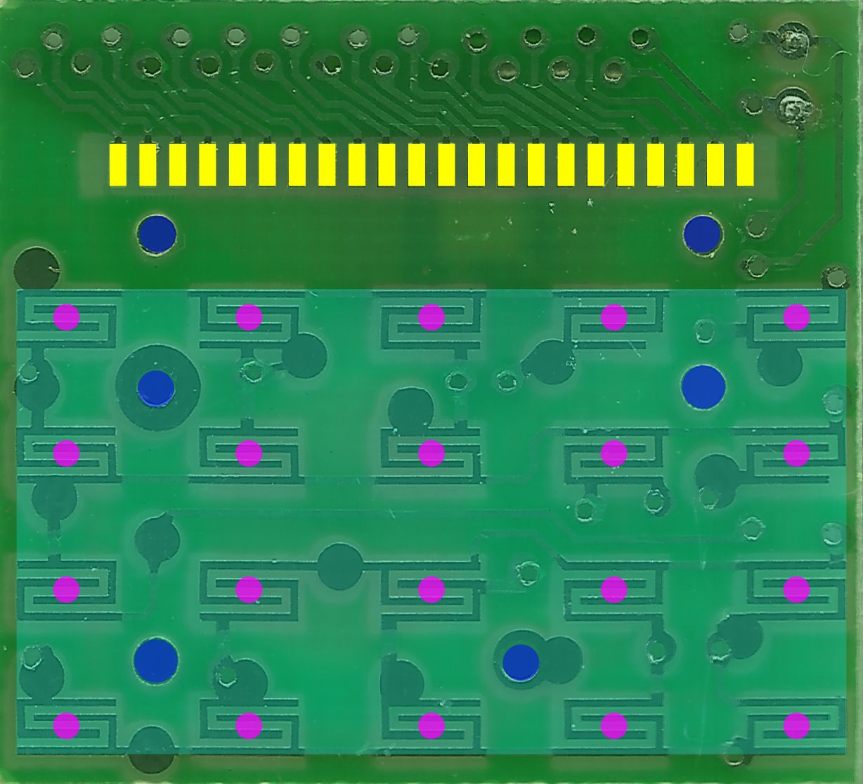
There are 1.1mm, 1.2mm and something around 1.4mm drill size holes on the PCB, either for screws or mounting poles of the plastic case. After pushing things around and trying to find a center I ended up with this colorful layered image.
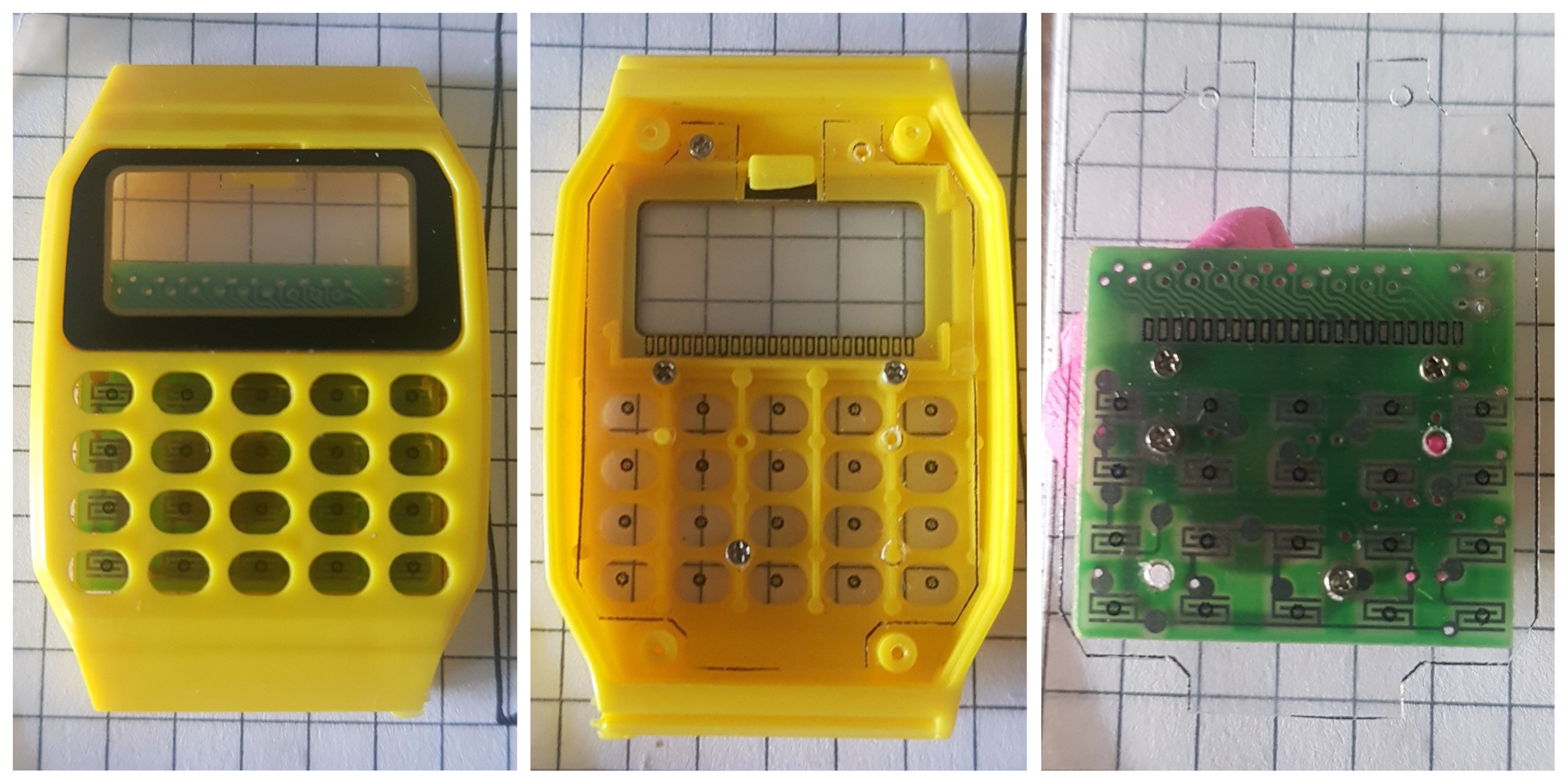
I continued with importing a photo of the case internals, so I can draw a new PCB shape with more real estate, using what I can get. We definitely want to add a side glowing LED and there are some free screw-holes that we can use. To test the PCB dimensions and mounting hole positions, I printed only the contours of all the elements onto a clear overhead projector foil. It helps to have small drill bits around, to probe the hole sizes.
Looks like the fit checks out :) Now I need to find out how to get that SVG into something that I can convert and work with in KiCad. Did you notice how many open source projects I've listed?
This is what the PCB now would kinda look like. I might remove the LCD holding tap and close that top opening as it does not really seem to do anything.
New PCB For Calculator Watch | Pinout Of The LCD
2021-07-17 20:21:53
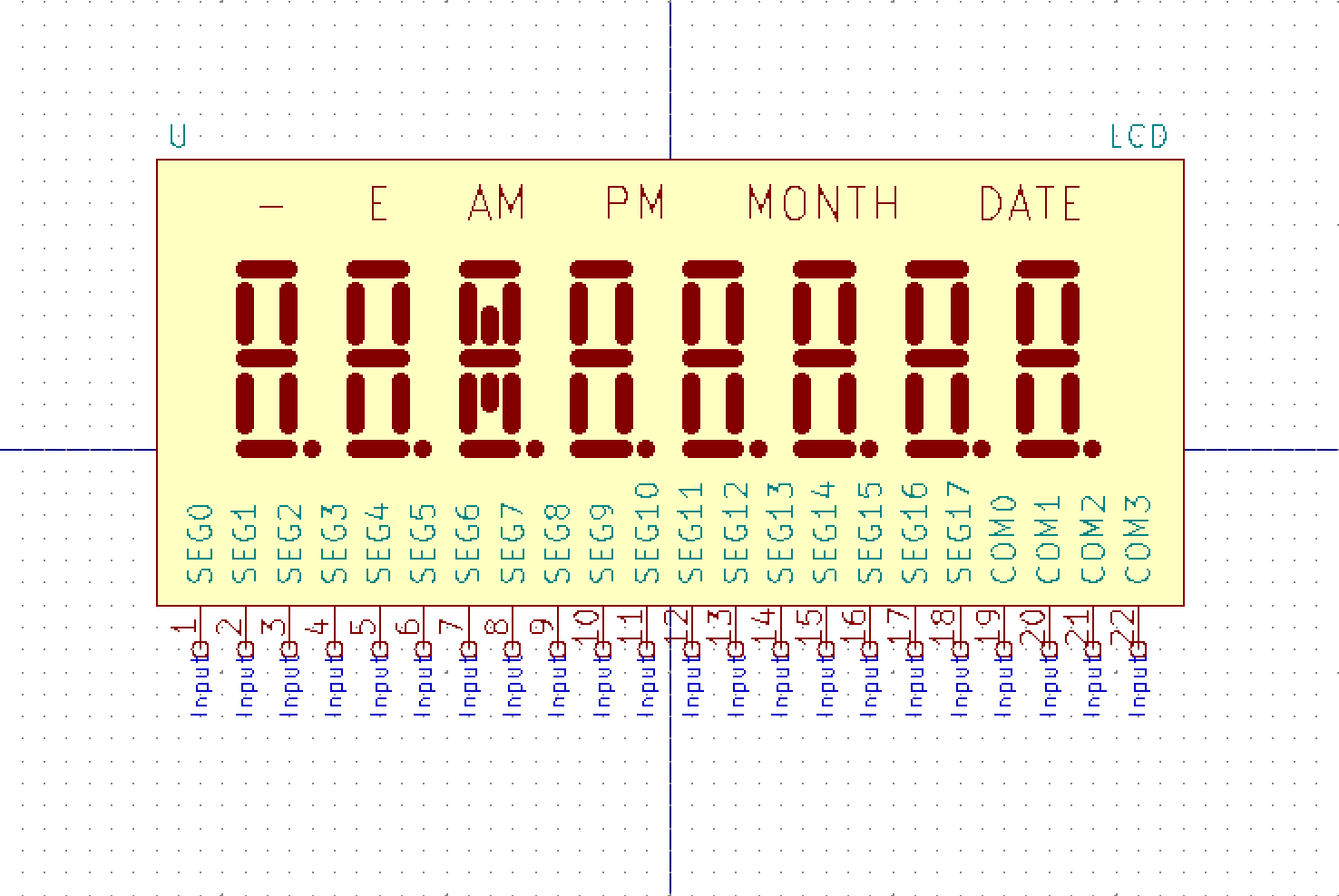
The blob chip on the PCB is on the other side of the contacts for the LCD of the PCB, so there are 22 vias that I was able to sand and solder to. I've cut the connection of the chip, so I basically ended up with a breakout board for the LCD. Because of it's "capacitive" nature the display showed something just by connecting the positive pin of the power supply to a segment pin (voltage not important as there was no circuit completed). At least I think that's the reason. I guess everyone has taken apart an LCD calculator and was fascinated that it shows something just by you touching the pads or pins of the display. Anyways, thanks to this "trick" I was able to see that the 22 pins of the LCD are 18 pins for groups of four segments and then 4 of course for one of that activated segment. Thee pinout is super straight forward, as the 4 common pins are the last 4 on the right.
Here's a screenshot of the KiCad symbol I'm working on right now
New PCB For Calculator Watch | Reverse Engineering the LCD controller
2021-07-17 18:54:09
Disclaimer: I have never before done anything with LCDs directly
There are three things that I've learned, that are essential to drive an LCD segment. For easier understanding just think of one segment with 2 pads or legs that you have access to.
There's a threshold voltage difference to achieve, where displays turn dark. For example the LCD in the watch needs either 3V or -3V and it activates.
The bias needs to be at 0V When you toggle your segment on one pin between 0V and 3V, the display is held at a bias of 1.5V - something displays don't like. What you want to to is something like this, to hold the bias at 0V:
PIN1
PIN2
Voltage
0V
3V
3V
3V
0V
-3V
You need to oscillate Running a single segment correctly means you could use a good old 555 timer, set it up to ring at 60-90Hz (need to check for correct frequencies) and use an inverter for the second pin for the right way to keep your LCD healthy.
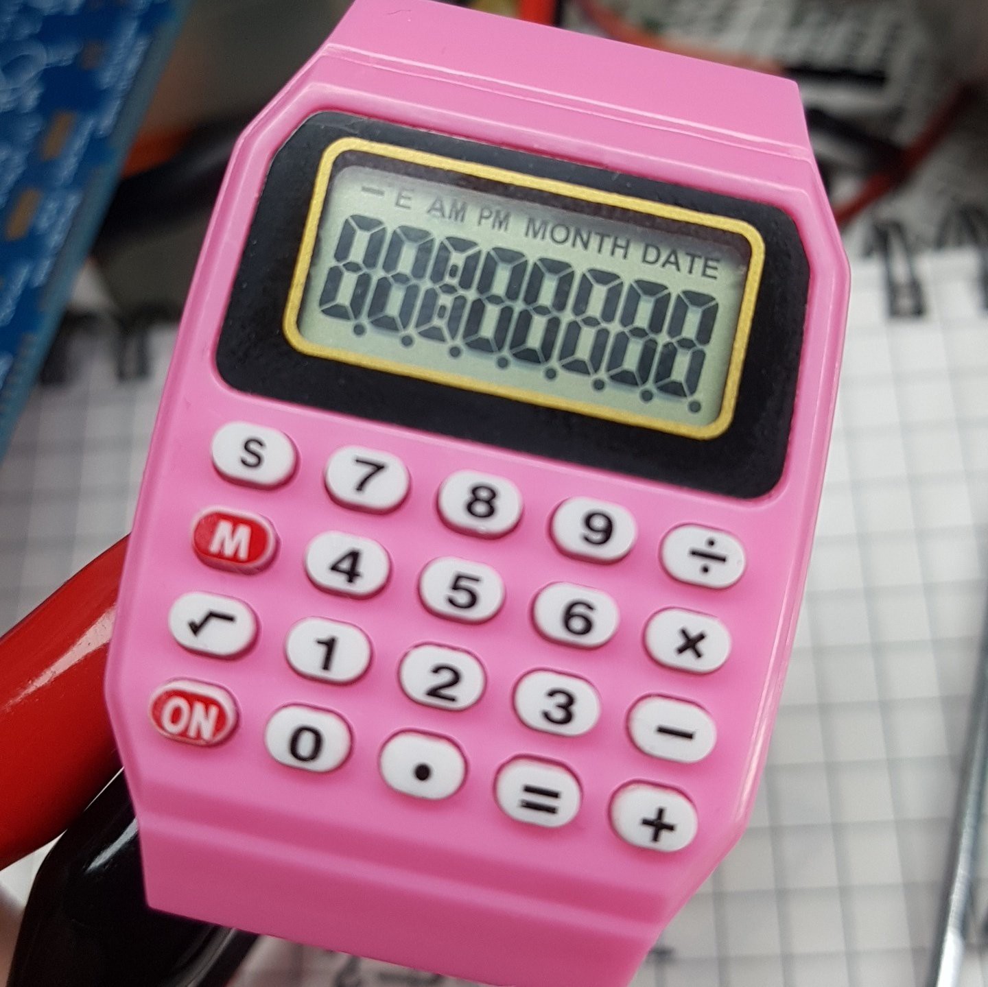
The Watch LCD
While I had it open for the first time, I accidentally had the power supply set to 2V and I was greeted with all the digits I can get. This threw me off so much that I thought the display would only run on 1.5V and any voltage above would lead to the display showing everything. So here I thought the SAML22 is out of the question, as it has a minimum voltage for the LCD of 2.4V. But it's a little bit more complicated than that!
I am one of those privileged humans with an oscilloscope, so I thought I might give it a quick look and see if the display really runs with 1.5V or rather wants something like 3V and the magic blob also does some voltage boosting. So I sanded away the solder stop mask from the vias on the board and soldered on some LED legs to connect the probes to.
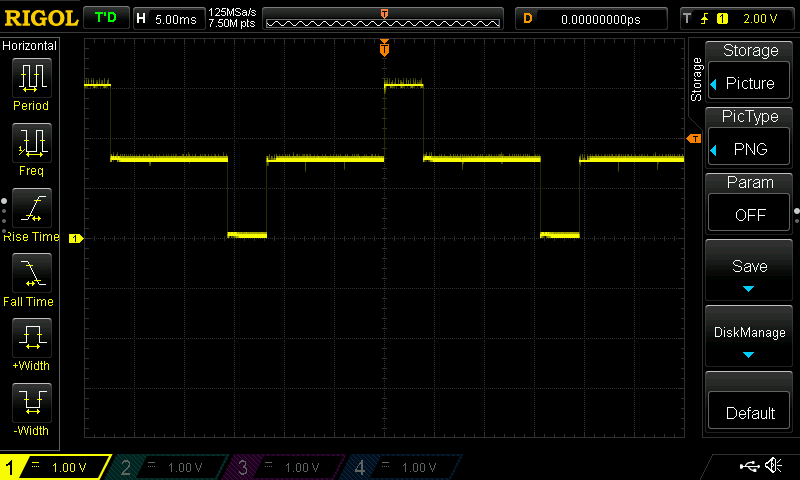
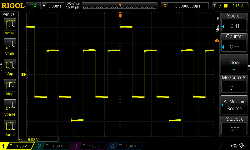
On the screenshot above is the voltage difference shown between one of the common segment pins and battery minus. First let's point out the obvious, this is between 0V and 3V, which is great news for using the SAML22! What you see here though is implicating a 1/4 duty wave with bias steps of 1/2 (what?).
The LCD has 4 of those common pins and 18 pins for segment quadruplets. You can probably spot the little indents that separate the long line into 3 areas, those are "timeslots" for the other common pins basically.
Above now is a screenshot of the voltages between one of the common pins and one of the segment pins. Here you can see Rule 2 being followed by having it oscillate around 0V. All the wavy stuff is really confusing though, just by looking at it, right? The important information for us is that the segment is activated, because we have a peak to peak voltage of 6V, meaning the segment is triggered by the 3V difference we talked about in Rule 1.
So what's the wavy stuff all about?
I don't really now :D but the SAML22 datasheet says that a "bias of 1/3" is preferred for a duty of 1/4. Reading further in the datasheet this means that you generate a step-wave of 1/3, 2/3 and full VLCD to talk to your LCD. The watch controller seems to use a bias of 1/2 for generating a "wave", that's why we see a step at 1.5V in the first scope screenshot. It's somehow necessary for multiplexing and keeping it AC.
I have modified regular nylon servos and noticed that the variable resistor from many tutorials have changed from an insert knob to a fixed metal knob. You have to drill into the gears with a 1.5mm drill and now the gear has too much play and the gears block because of the play the gears grind at each other in an angle. So the sensible idea here was to make little M1.5 spacers / washer from LED / resistor legs.
This is not something you want to repeat for all the servos of your robot army! So just buy continuous servos and be happy that you saved an hour by paying a dollar more!
Since the knob rod is fixed, it's tough to even remove the resistor from the controller - so I just soldered directly to the motor and ended up with a geared 6V motor. You can buy these on your own, too! Look for 6V N20 motors.
ESP based robots | some specs
2021-06-21 16:11:05
The ESP32 cam board features an ASM1117-3.3V regulator. This regulator allows for 12V input voltage, but also has a dropout voltage of 1V. With only one cell this would technically not even work, as the 3.3V + 1V means we're already above 4.2V of the charged cell. The ASM1117 works well with 5V though, so boosting the voltage might seem feasible.
Let's just say you want 600mA from the 5V source you've just boosted, or 3W. With a charged battery (4.2V) and let's say a perfect, lossless converter you would draw current at 712mA. Looking at a voltage of 3.2V this would mean pulling 938mA.
With two or four servos/motors (stall current needs to be measured), an LED that takes 130mA and an ESP32 with Camera coming in at 180mA - this setup can brownout quickly.
With two cells I hope to be able to power the servos at 6V. I want to later verify, that a 2s cell at 450mAh should hold up longer than a single cell battery at 900mAh.
burning firmware onto an ST-Link to burn firmware onto anything else
2021-06-07 20:37:26
at least I'm trying to find that out. The clones from aliexpress are supposed to be only able to program st chips. But I want to use it to program some SAMD-21 chips. Never done that as well. So this is a link drop first. Figuring it out for MAC OS.
to compile arturos fine firmware, you need to add the ARM stuff to your path, otherwise you compile and wonder why he wont find "gcc-arm-none-eabi" again.
export PATH="$PATH:/Applications/ARM/bin/"
D1867G based keyboard hacks | single channels
2020-12-17 22:41:21
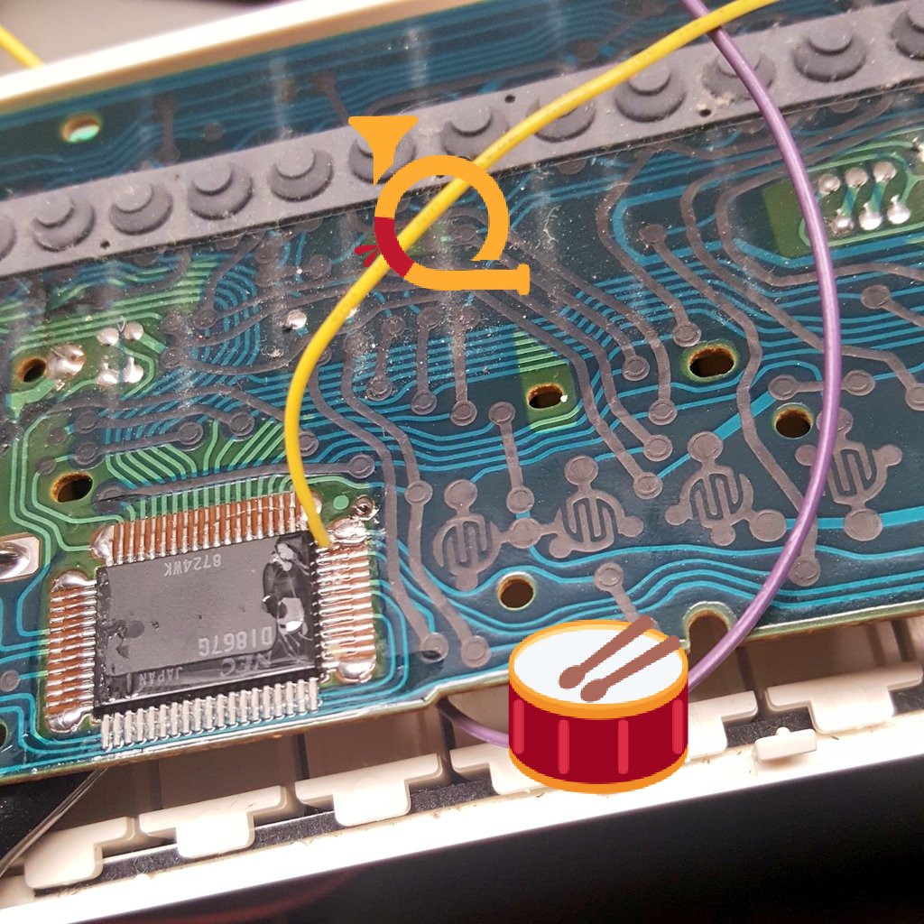
The tone / notes are mixed with the drums together and amplified, put through the speaker. Before that you can grab them from pin 12 (voice) and 13(drums). There might be an envelope channel on pin 11 - at least that;s what was said in one of the very well produced "keen on keys" videos.
D1867G based keyboard hacks | Adding an octave switch
2020-12-17 22:31:55
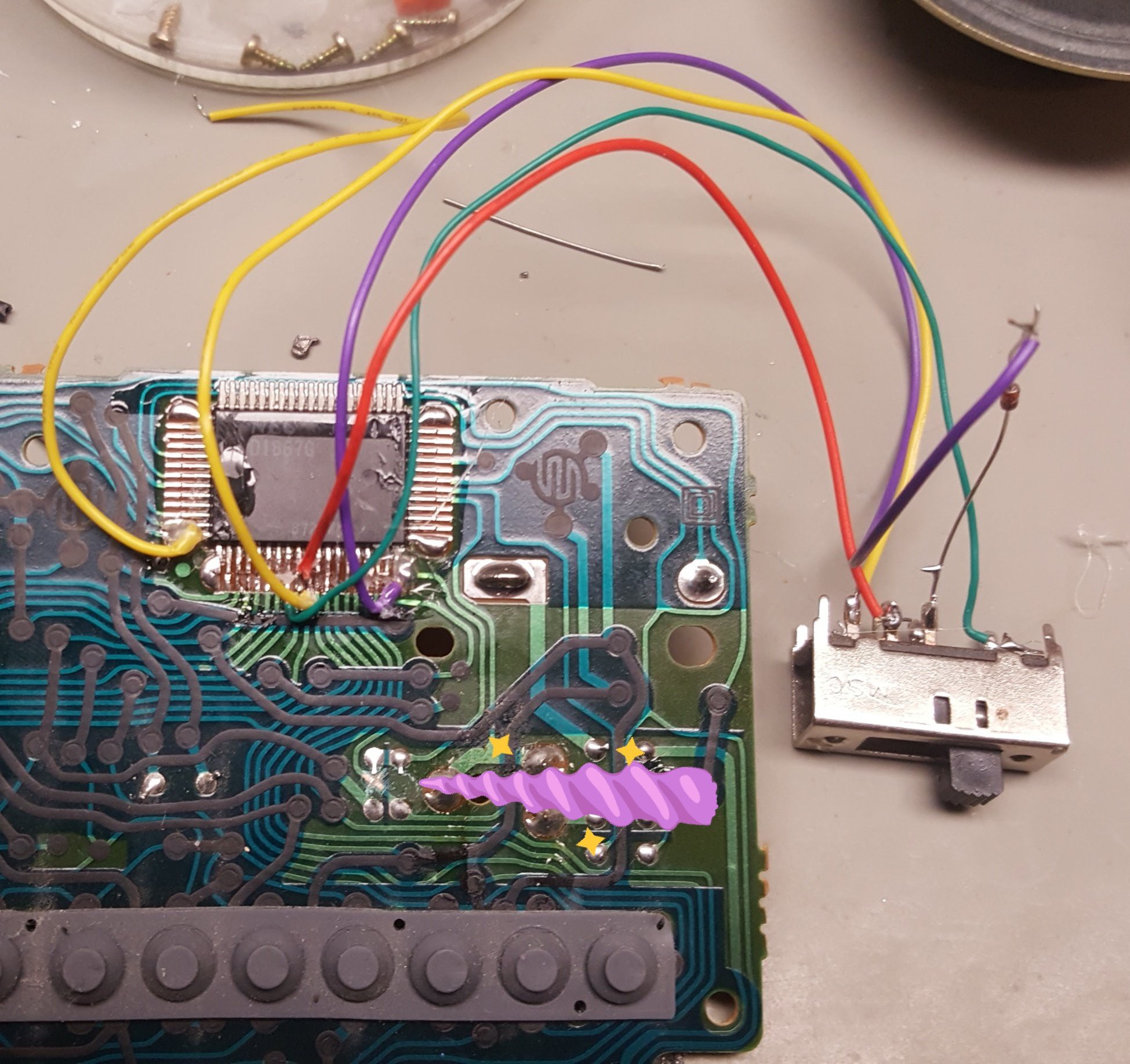
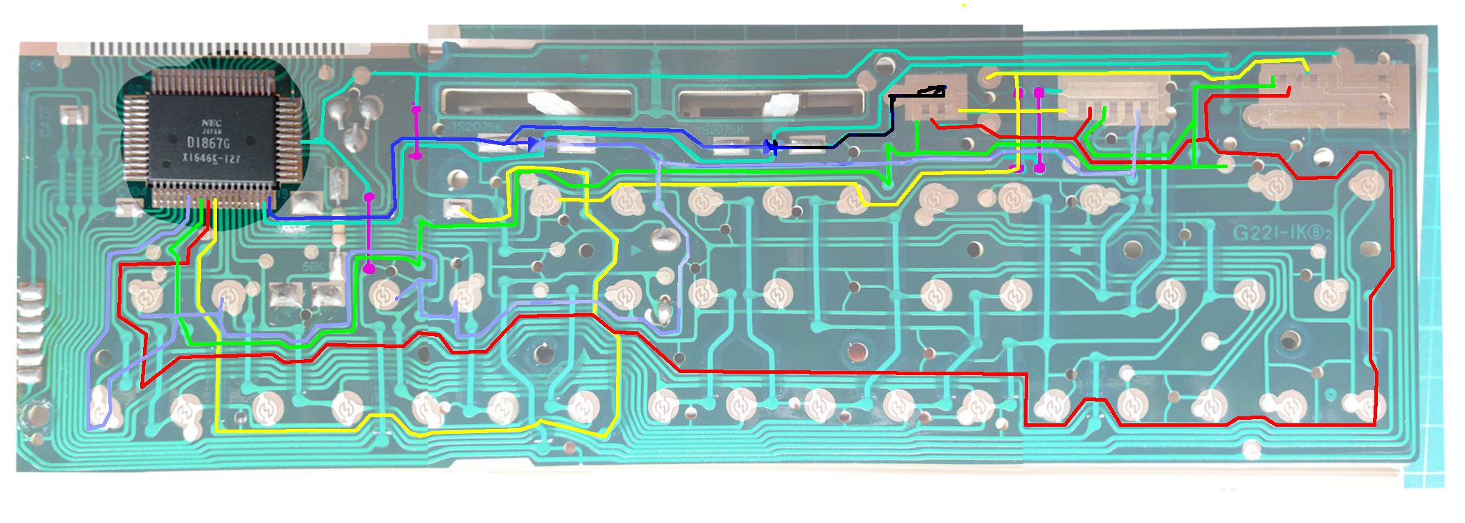
This is 3 pictures of the PCB of a VL-Tone VL-1 patched together to one. After a shoutout on twitter people were taking apart their VL-1s for me and took pictures, what a great thing! The main connections for the switch are on the bottom.
The PT-10 that I own has the same chip in the same case, so I wanted to see if I can add something to the keyboard, that wasn't there before. Wait, did I hack something?
Counting from the bottom left, pin 8, 9 and 10 are the octave switches, connected through a diode and a 3 way switch to the very last pin. You (sadly) have to cut where the unicorn is pointing to, but it's reversible if you really need to do that.
Next up should be tracing the ADSR switch, to get a new instrument out of it. At one point I need to see if I can connect an LED display to replace the LCD.
LAMEBOY - another ESP12 handheld | Deauther ordeal
2020-08-24 21:12:14
I finally found my 2017 modified version of the deauther and added it to the download section. Use at own risk, don't come to me or Spacehuhn for advice. This is as is. Use it on your own tech only. Don't make people hate you because you want to "jam" your neighbors. Be nice and responsible.
Proud of the added "scan" for the button IO expander, as I've used different versions with different addresses over time.
THT feather with ATMEGA8 | reset mod by @danjovic
2020-08-18 09:35:45
I've added a modification by @danjovic to the download section. It adds a reset button to the updated schematics. I still haven't come around to actually test my own board, but the first version was already verified by someone else on twitter.
THT feather with ATMEGA8 | Boards are in and a small surprise
2020-05-24 22:16:50
Thanks to OSHPark the boards got here quickly, but I'm still waiting on some parts like the regulator, to populate the PCBs. I noticed that one of the resistors seems unnecessary, I've copied it in from the 5V design and forgot to remove that. Maybe I'll put a pull-up resistor on the reset pin in its place - although I do believe there's an internal pull-up resistor anyways, albeit weak.
Someone managed to order and build this project before I even had the chance to solder something together! Turns out there was a minor mistake in the design where two ground plane fills were separated. The V-USB firmware is reported to enumerate - yay :)
Not sure what has happened when I soldered the boards, but I never really got them to work properly. I just spend an hour on reworking and cleaning a board, but I've must have killed the chip doing that. Before it was accepting the bootloader, but now both boards are completely gone.
One spare board from the first batch is missing the chip and I'm considering to remove everything what's on there, cleaning all the pads and try everything with a low temp solder paste and new parts. It still bugs me that everything is running off of the battery voltage on the arduboy.
Or I'll just slap a known Atmega32u4 board on there and call it a day.

 The PT-10 that I own has the same chip in the same case, so I wanted to see if I can add something to the keyboard, that wasn't there before. Wait, did I hack something?