Did some more "perfect scenario" calculations for the possible frame rates, after failing math hard at supercon, thinking that I am sending out half a million bytes for a frame on the cube.
12 displays
192 bytes of data - 12x16 pwm values for 64 LEDs, even though I'm using only 51 LEDs
every byte is followed by an ACK from the peripheral
So we have 12 * 192 * 9 bits to fly over of raw data, not including addressing and setting PWM page. At a 400kHz clock speed or 400000 bits/s we arrive at a hypothetical 19.3 fps.
What did I change to get here? After sending the data for the LEDs in bursts, I arrived at roughly 10fps and hooked the cube up to the oscilloscope to see what's going on. Turned out the clock was at roughly 200kHz instead of the expected 400kHz o.o
the edges of the data are not sharp at all
This might look very obvious at first sight to some, but the spikes aren't supposed to look like this and there is this magical thing that you can add to I2C lines, when it looks like that - I forgot about pull-up resistors! To allow for a fast rise you need resistors connected to VCC to help rise the potential of the capacitive natured data and clock line. To be honest I have no idea how to better explain this, but I hope the image helps a bit.
I've added 2.2k resistors to the module and suddenly arrived at 16fps! I might be able to go even faster with a different controller, but I still like the XIAO NRF52840 sense too much with all its features that I have yet to use :D
LEDodecahedron | slow libraries everywhere
2022-11-15 13:14:15
I've spent 3 hours hunting down the speed settings for I2C on the Seeed XIAO NRF sense board in Arduino, but couldn't find it. My goal was to have a frequency of 1MHz for I2C instead of 100kHz, but so far there was no chance.
it's quite frustrating that I still have no idea where the seeed library based on mbed for the XIAO NRF sense defines how the I2C works with the wire library in Arduino. I found so many registers and values where I was "aha! That's the two wire interface speed value that I was looking for!" but then nothing changed when I edited the sdk_config.h file.
The other thing that slows down the animations is the code for writing to the LEDs. Looks like the code first writes a select page and then writes a single byte for the LED pwm value. There's definitely optimisation possible in streaming plenty bytes after selecting a page, instead of ping pong-ing that often to effectively set one byte.
[UPDATE] 10 frames per seconds reached
managed to send complete frames to the I2C controllers and now reach 10 frames per second on the NRF52840 board. After some datasheet reading I'm not so sure I can easily reconfigure the I2C to go 1MHz on the NRF52 and ordered an ESP32-S2 QT PY board to play around with. Last hope for the NRF52 is using the adafruit board libraries instead of the XIAO mbed library as I am fairly certain I saw code there that makes more sense. Would be nice to be able to use the NRF board with all its sensors (mic+accelerometer) on board.
FLASHING LIGHTS WARNING
Penghicorn | dimensions
2022-09-21 12:24:55
Note to self, the distance between the SAO headers on my first oshpark penghicorn badge is 4.1inches (rounded) or 104.177366mm according to eagle file imported to kicad. Not sure I will make something with that.
im-me messenger - 12 years later | trying to get the GoodFET running on mac
Found a good starting point to talk with the MSP430, but sadly it runs into a weird bootloader password issue.
goodfet.bsl -P ./goodfet.hex --fromweb
Use -h for help
Use --fromweb to upgrade a GoodFET.
MSP430 Bootstrap Loader Version: 1.39-goodfet-8
Invoking BSL...
Transmit password ...
Use -h for help
Use --fromweb to upgrade a GoodFET.
MSP430 Bootstrap Loader Version: 1.39-goodfet-8
Invoking BSL...
Transmit password ...
Traceback (most recent call last):
  File "/usr/local/bin/goodfet.bsl", line 1987, in
    main(0);
  File "/usr/local/bin/goodfet.bsl", line 1887, in main
    bsl.actionStartBSL()
  File "/usr/local/bin/goodfet.bsl", line 1166, in actionStartBSL
    self.txPasswd(self.passwd)                  #transmit password
  File "/usr/local/bin/goodfet.bsl", line 1136, in txPasswd
    wait=wait)           #if wait is 1, try to sync forever
  File "/usr/local/bin/goodfet.bsl", line 801, in bslTxRx
    rxFrame = self.comTxRx(cmd, dataOut, len(dataOut))  #Send frame
  File "/usr/local/bin/goodfet.bsl", line 480, in comTxRx
    rxHeader, rxNum = self.comRxHeader()        #receive header
  File "/usr/local/bin/goodfet.bsl", line 386, in comRxHeader
    if not hdr: raise BSLException("Timeout")
__main__.BSLException: Timeout
aha! So the tutorial uses a capital P where the flag should be a small p. Or not, maybe the password stuff is set somewhere else or while compiling. writing the ./prebuilt firmware worked.
board=goodfet42 goodfet.bsl -p goodfet.hex
Well that wasn't really a solution, but somehow I got it to except the firmware, probably by using the "fromweb" flag for it, where it wasn't confused by all that.
im-me messenger - 12 years later | but first, we must build a goodFET42
2022-07-18 21:44:29
Sure, I could try and do the same hard work that plenty people have done before me, do miserably and fail - or I could just try and get stuff from back then working. So within chip shortage I tried to get hold of the MSP chip that's featured on the GoodFET, a DIY JTAG and more probe, that isn't obtainable anywhere. Thankfully everything I needed was accessible and so I started redesigning the GoodFET in KiCad, swapped some parts and added rounded corners basically and ordered the boards at OSHpark. Why did I do that? Because all the tutorials from 2010 basically start with "connect your GoodFET to the im-me messenger" and well I need one then, of course.
fixing a bad motivator | the dome decoder
2022-05-16 10:27:33
Had to share this beauty
fixing a bad motivator | more lights
2022-05-16 09:57:57
R2-D2 has some fancy lights in his head, but here with the 40% scale they resulted to holographic stickers instead. I might change that with some fibre optics (lichtleiter for ebay) or replace it with an OLED - not sure yet! both displays come together to 225 LEDs.
fixing a bad motivator | Power section and motor control
2022-05-15 20:45:48
R2-D2 seems to run on 3 voltages:
6V for the motors
4.5V for the logic
1.5V for clock or memory keeping
From other projects I've learned about drone parts, known as BECs that convert LiPo voltages to 5V and most often 12V. I want to modify the HTPDB-XT60 module so it will convert to 5V and 6V instead, so I can use a 2-cell LiPo pack.
To control the motors I will use a DRV8838 single motor driver for the dome and a DRV8833 dual driver for the leg wheels
fixing a bad motivator | what's inside
2022-05-15 01:30:09
This thing is packed with interesting stuff!
Dome
PIR sensor
2 microphones, 1 left and 1 right (for body reaction only?)
LED for the beamer
two LEDs in the front
ultra-sonic range finder
PIEZO in the top (tap to wake up)
Body
Speaker
another microphone
dome motor
3 IR photo sensors for dome position check
leg motors
switch acting as "brake" / bolt
Fixietube - Fake Nixie Tube displays | new bulb and missing schematics
2022-01-06 20:38:55
Lot's of older projects I designed in Eagle, but I'm not using that anymore. Recently I found some cool jars and wanted to make a new bulb, but had no idea what the correct arrangement of LEDs was. So here are screenshots of the schematics to work with, done on my old computer.
LEDodecahedron | mistakes been made
2021-12-30 12:38:40 I missed that one LED wasn't correctly placed in the schematics and one connection is missing. Have to go in with magnet wire and fix that on all 15 boards :)
LEDodecahedron | shapes
2021-12-17 20:33:31
Always tough googling something when you're looking for the name to google in the first place. I needed the "dihedral angle" of a dodecahedron, meaning the angle between the sides / faces of the body. It's 116.56505°. The cool thing is, with that Angle I can basically nibble away all sides and have the perfect folding angle for this! But for now I just eye-balled it.
screenshot of openscad, a small frame for a pentagon shaped object is shown. A little bar in an angle is close to it.Screenshot that compares the angle of the block to the manually set angle of the frame, so it can fold up to a dodecahedron. Angle is basically indistinguishable.
WIFI Game Boy Cartridge | Infomercial: someone succeeded in creating a WiFi cartridge
2021-12-16 15:27:22
I've been recently contacted by Sebastian, asking me things about this project because he made a WiFi cartridge. We talked a bit about the hurdles I faced and now there's a video of his project out and here's a link to his blog post as well.
New PCB For Calculator Watch | ugh how did I do it again? LED's get to blink
2021-12-15 21:58:58
This seems to be the setup for my controller and the chip, as the SAML22 works with the at91samd target.
#!/bin/bash

openocd -f interface/cmsis-dap.cfg -f target/at91samdXX.cfg

# in new window

openocd -f bootloader-sensorwatch_m0-v3.7.0-12-gf92e7dc.bin
LEDodecahedron | First boards are ordered after 2 years
2021-12-15 18:02:08
Since I'm visiting family in America, I found some time to tackle those weird PCB designs that I always talk about, but never do. Two years ago I made the #Do or Donut SAO , which rhymes with this project as in me using the same(?) chip to control a bunch of LEDs. When I started this, two things came clear: I did not want to use more than one chip on a board and that basically meant going for 51 LEDs. You can read up on all my minor design choices and routing issues on twitter: https://twitter.com/davedarko/status/1468990742316167171
The distance between the LEDs in not the same at all, as the five triangles that make up the pentagon have angles of 72-54-54 degrees and are there for not symmetrical in all the directions. But I'm happy with the spacing, so I proceeded.
I should be able to power everything with a considerate brightness from a smaller battery, as was the LED cubes I took inspiration from. Heat should not be a problem either, but we'll see about that. The dodecahedron will have a height about 5cm.
The chip can have up to 16 addresses, so that's perfect for controlling the 12 boards with one IC. I have not calculated the frame rates of anything, the chips talk I2C with up to 1MHz, to up to 12x16 LEDs.
New PCB For Calculator Watch | First woopsie on the PCB
2021-10-29 14:59:30
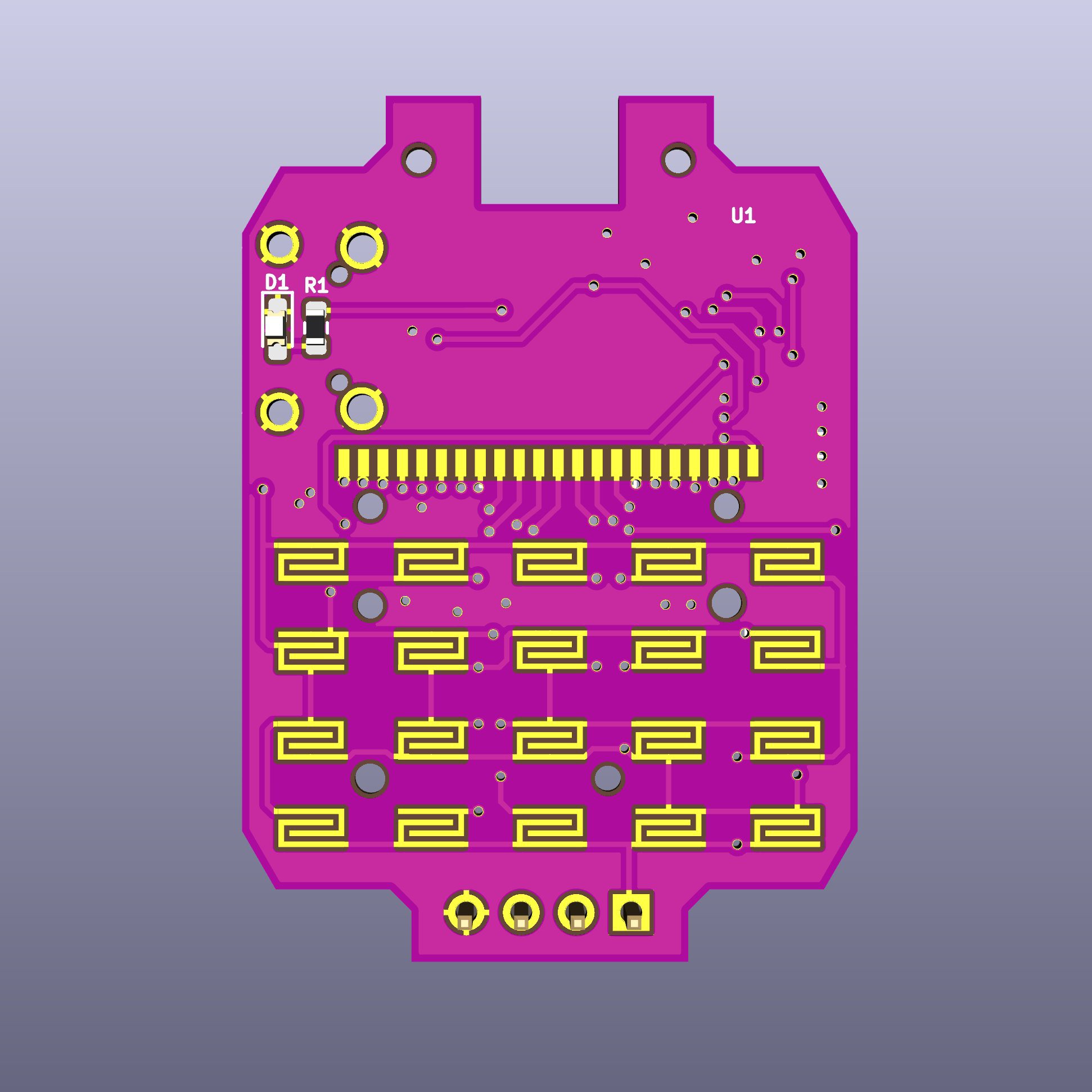
By now I've realised that I forgot to add all the 20 diodes to make the charlie-plexed keyboard function. In the current arrangement there will be no way of telling if I have pressed the button connected to the 1-2 pins, or the 2-1 pins.
This basically made me choose between upscaling the SAML22 to the version that Joey Castillo is using for his amazing casio F91W replacement boards. I could also try to place twenty diodes all over the board. Or ten and do some crazy "check if both combinations are working or just one" firmware. In the end I used an IO expander that is dedicated to read keyboard matrices, got some TCA8418RTWR on aliexpress, as they're out of stock everywhere else.
Soon I will try to get the UF2 bootloader running on the watch and then start programming it via the USB socket. First I need to cut out room for the plug though :)
New PCB For Calculator Watch | Dipping my toes in ARM programming
2021-10-09 14:45:53
So many things to learn are ahead! Thankfully there's a project out there, that is using the SAML22 for a watchproject for use with LCDs, the Sensor Watch by Joey Castillo. https://github.com/joeycastillo/Sensor-Watch
Apparently openOCD is a thing people use to slap those sweet binary files onto plenty other ARM processors and you can get that over here https://openocd.org/
To familiarise with openocd, I tried to work with some commands and get to know what's going on. I tried to list all possible adapters and see what's out there and if my programmer is on that list. The space between "adapter" and "list" is confusing openOCD, so be sure to use one of these working ways to write it:
openocd -c "adapter list"
openocd -c adapter\ list
One little thing that took me off-guard: the openocd works like a server that you connect to, but you first have to start it with the settings set to your target micro controller. Then you send the bin / hex files to the controller via a tcp or telnet connection.
New PCB For Calculator Watch | First boards ordered
2021-09-13 14:06:13
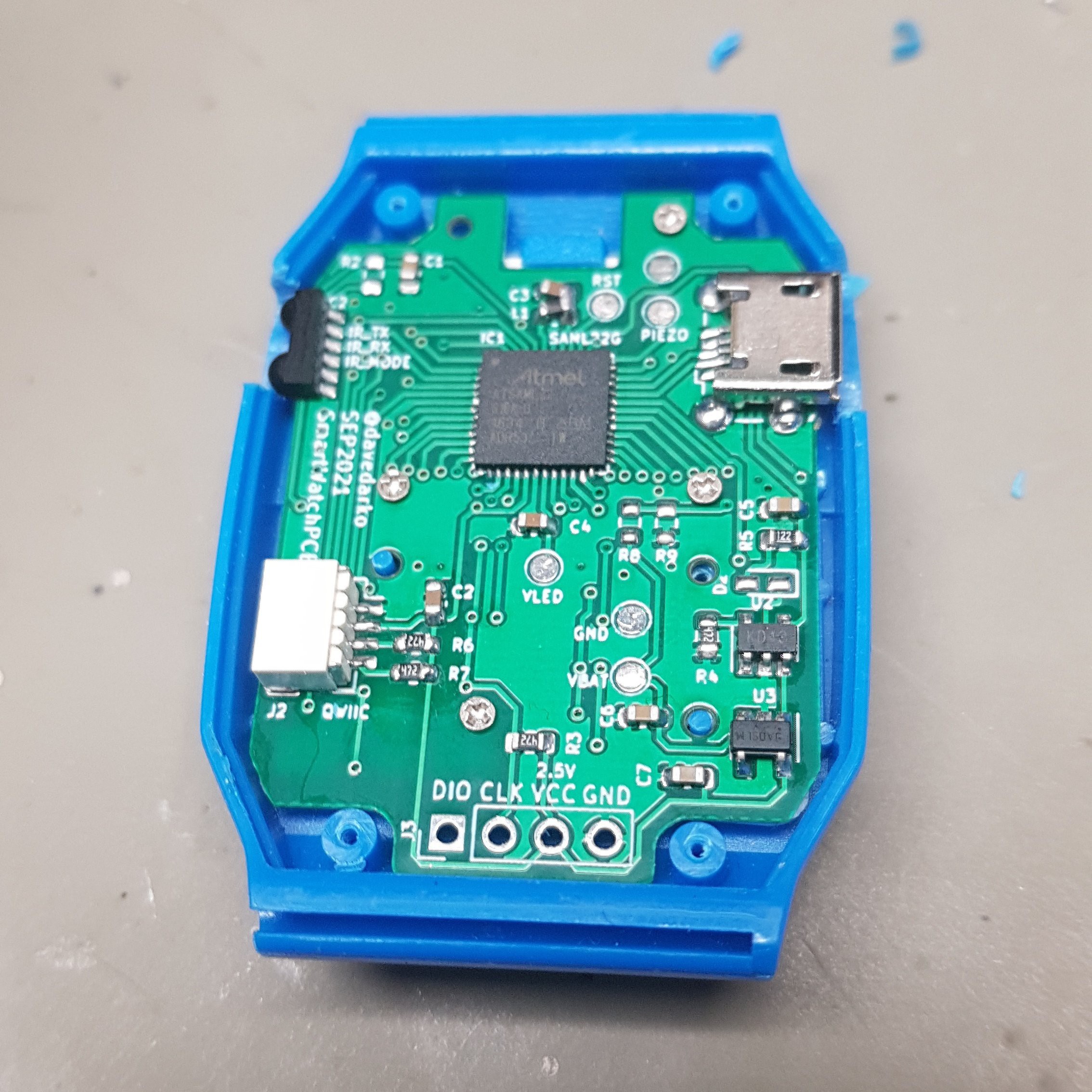
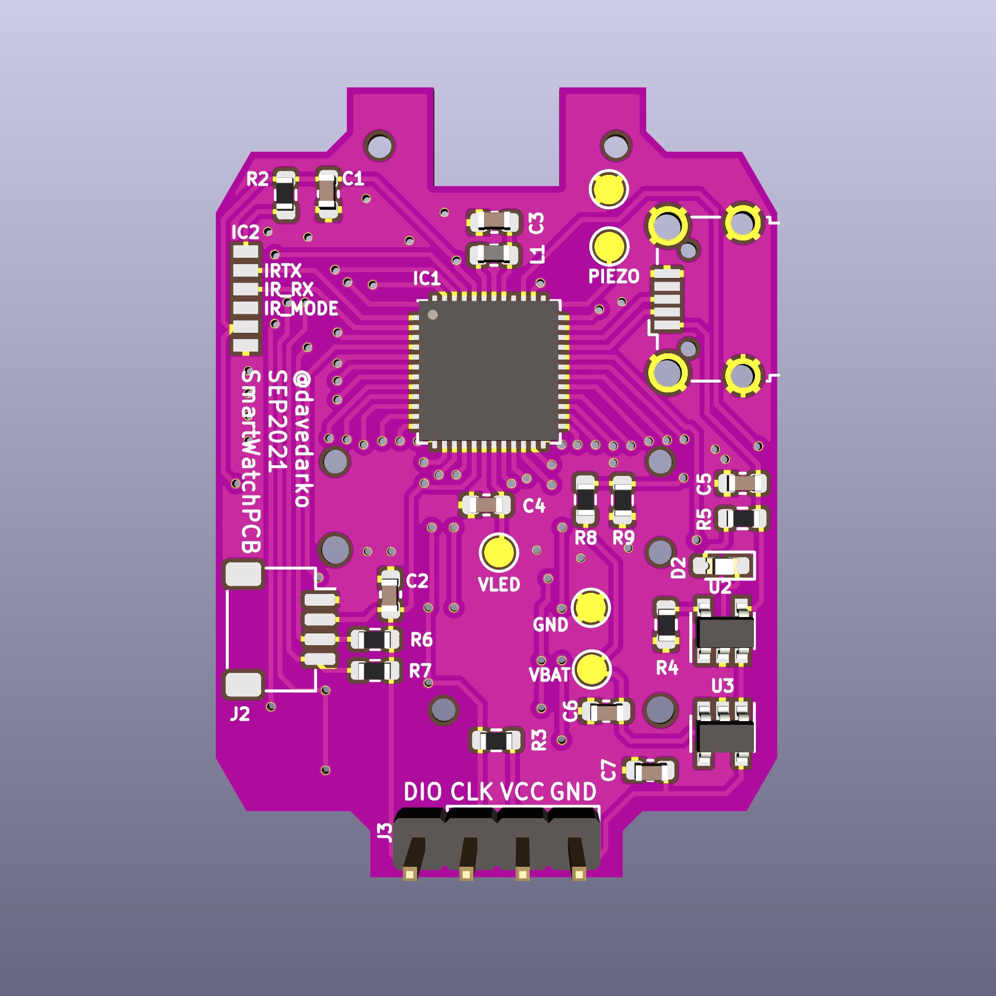
After a longer break I managed to draw the symbols and footprints of the SAML22G and the IR transceiver module, so I would not have to rely on licenses of external sources. With that I was able to finalise a first prototype board and send it to JLCPCB for production. With the recent pink PCBs that boardhouses now produce I was very tempted, but I opted for a set of 5 green PCBs instead. I decided to run the board on 2.5V, which makes it easy for the AP2112K to work with the battery voltages of a LiPo battery, without running into dropout voltages first. There is some room and I'm tempted to add a footprint for a compass chip in the future, but I can always just connect to the QWIIC connector, as long as they are okay with 2.5V. Should have thought about that.
I've started to work in KiCad and love to use the buzzard library for labels now. The 16 step sequencer is basically two zynthias (CD4028, CD4029, CD4051) that either count to 8 together or to 16 one after the other. The two stages had to be mixed with an LM358. I tried a TL072 before, but that didn't seem to work. Maybe the LM358 likes DC better as I did not supply negative 12V to the board. I'm using a CD4070 XOR logic gate to be able to invert the second stage with a switch. Still have to route 48 air wires, but I'm getting there. This is a revision, I had the first board for 8 months and was only yesterday able to fi the mixing part of the two stages.