all years
202620242023202220212020201920182017201620152014
2211152313307215210213462
newer 2 / 7 older

Me building projects from hackaday.io | R-2R DAC inspired by tiny7 by al1

2015-11-04 10:51:44

Inspired by #tiny7 by @al1

Following @Elliot Williams on youtube I noticed his next "logic noise" HaDblog post will feature R-2R DACs and an hour later I had this idea for a little project, using a shift register with some 6.8kOhm resistors I have too many of. Since I really liked the Idea of using the accessible ISP header on arduinos to send data to the shift register like the #tiny7 by @al1 does, I had to put this on a protoboard. Expect some weird sounds to follow, because they are nowhere near to be accurate with 5% tolerance resistors. This just screams for a self checking arduino script that writes data out and checks the output with analog input.


Heimdall - dumb remote home | Prototyping Pi shield AND LVDS converter are in

2015-11-03 21:10:56

for power monitoring stuff I bought a prototyping shield/hat for the raspberry pi. I'll probably put an arduino onto it, to control some WS2812b LEDs. And some pwm control for the mini fan.

[update]

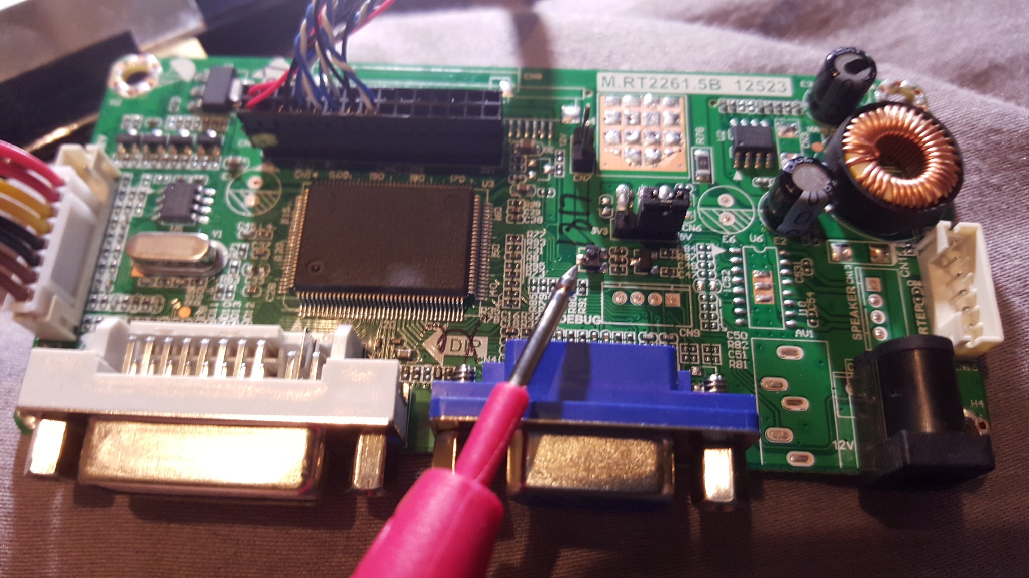
I also got a LVDS converter board for an old macbook screen. I just hooked it up and there it was, FREE blue magic smoke! First inspection let's me assume that the LVDS connector has a cable that shorts the inverter leads. I'll have to write the guy that sells it, but my hopes are low that he actually knows what the problem could be. So let's hope for a refund and a still working display.

Me building projects from hackaday.io | ​Nyan Board by Radomir Dopieralski

2015-10-31 12:11:33

#Nyan Board by @Radomir Dopieralski

[UPDATE] Video and code added

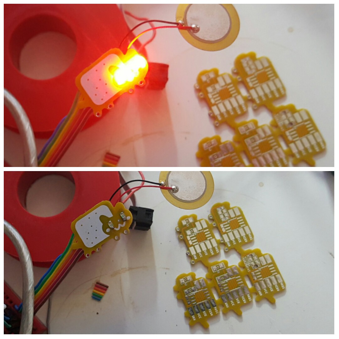
So this should be an easy one, right? Oh how I failed. I'm still not getting sounds out of it, after I played around with libraries and different Versions of arduino. It's always tones and timers that get me.

I first thought the pads next to the attiny45/85 where a pullup resistor - d'oh. Of course it didn't do anything. Now it at least blinks.

To fit on an attiny45 I had to change the code a bit.

this code works, see the comments:

const int LENGTH = 27;
const int NOTES[] PROGMEM = {
    65, 67, 70, 67, 74, 74, 72, 65, 67, 70, 67, 72, 72, 70, 69, 67, 65, 67, 70,
    67, 70, 72, 69, 65, 65, 72, 70
};
const int DURATIONS[] PROGMEM = {
    25, 25, 25, 25, 75, 75, 15, 25, 25, 25, 25, 75,
    75, 75, 25, 5, 25, 25, 25, 25, 100, 5, 75, 25,
    100, 5, 100, 200
};

void play() {
    float bps = (60.0 / 120) * 1000.0;
    for (int i = 0; i < LENGTH; ++i) {
        int note = pgm_read_word_near(NOTES + i);
        int duration = pgm_read_word_near(DURATIONS + i);
        
        int hertz = (int) (pow(2.0, ((note - 69.0) / 12.0)) * 440);
        tone(4, hertz, (long) (duration * bps / 100) - 10);
        delay((long) (duration * bps / 100));
        toggle_eyes();
    }
}

void toggle_eyes() {
    PORTB ^= ( 1 << PB3 );
}
 

void setup() {
    DDRB = ( 1 << PB3 );
    DDRB = ( 1 << PB4 );
}

void loop() {
    play();
}
#include "pitches.h"
#include <avr/pgmspace.h>


const int FREQ[]  = {
    REST, NOTE_AS4, NOTE_AS5, NOTE_B4, NOTE_B5, NOTE_CS5, NOTE_CS6, NOTE_D5,
    NOTE_DS4, NOTE_DS5, NOTE_DS6, NOTE_E4, NOTE_E5, NOTE_E6, NOTE_FS4,
    NOTE_FS5, NOTE_GS4, NOTE_GS5,
};

const signed char INTRO_NOTES[] PROGMEM = {
9, 12, -15, -4, 9, 12, 15, 4, 6, 10, 6, 2, -4, -15, 9, 12, -15, -4, 6, 2,
4, 6, 13, 10, 13, 4, 0
};

const signed char MELODY_NOTES[] PROGMEM = {
-15, -17, 9, 9, 0, 3, 7, 5, 3, 0, -3, -5, -7, 7, 5, 3, 5, 9, 15, 17, 9, 15, 5,
9, 3, 5, 3, -9, -15, 17, 9, 15, 5, 9, 3, 7, 9, 7, 5, 3, 5, -7, 3, 5, 9, 15, 5,
9, 5, 3, -5, -3, -5, -15, -17, 9, 9, 0, 3, 7, 5, 3, 0, -3, -5, -7, 7, 5, 3, 5,
9, 15, 17, 9, 15, 5, 9, 3, 5, 3, -9, -15, 17, 9, 15, 5, 9, 3, 7, 9, 7, 5, 3, 5,
-7, 3, 5, 9, 15, 5, 9, 5, 3, -5, -3, -5, -3, 14, 16, -3, 14, 16, 3, 5, 9, 3,
12, 9, 12, 15, -3, -3, 14, 16, 3, 14, 12, 9, 5, 3, 14, 8, 11, 14, -3, 14, 16,
-3, 14, 16, 3, 3, 5, 9, 3, 14, 16, 14, -3, 3, 1, 3, 14, 16, 11, 12, 9, 12, 15,
-3, -1, -3, 14, 16, -3, 14, 16, 3, 5, 9, 3, 12, 9, 12, 15, -3, -3, 14, 16, 3,
14, 12, 9, 5, 3, 14, 8, 11, 14, -3, 14, 16, -3, 14, 16, 3, 3, 5, 9, 3, 14, 16,
14, -3, 3, 1, 3, 14, 16, 3, 12, 9, 12, 15, -3, -5
};

#define BEEP_PIN 4
#define LED_PIN 3
#define SPEED 1500


void toggle_eyes() {
    static bool blink = false;

    digitalWrite(LED_PIN, blink);
    blink = !blink;
}


void play(const signed char *notes, const unsigned int length) {
    for (unsigned int n = 0; n < length; n++) {
        signed char f = pgm_read_word_near(notes+n);
        int d;
        if (f < 0) {
            d = SPEED / 8;
            f = -f;
        } else {
            d = SPEED / 16;
        }
        tone(BEEP_PIN, FREQ[f], d);
        delay(1.3 * d);
        noTone(BEEP_PIN);
        toggle_eyes();
    }
}


void setup() {
    play(INTRO_NOTES, 26);
}


void loop() {
    play(MELODY_NOTES, 216);
}

Me building projects from hackaday.io | Pro Trinket USB Keyboard by Stefan Lochbrunner

2015-10-28 19:32:03

#Pro Trinket USB Keyboard by @Stefan Lochbrunner

[2015-10-31] started building

[2015-11-07] encoders are in, finally got it working (video proof)

When [Stefan] asked for one of my #Ignore this ESP8266 board 's, he send me one of his #Breadboard Widgets and I also asked for one of his Pro Trinket boards, since I had one or two trinkets in my drawer.

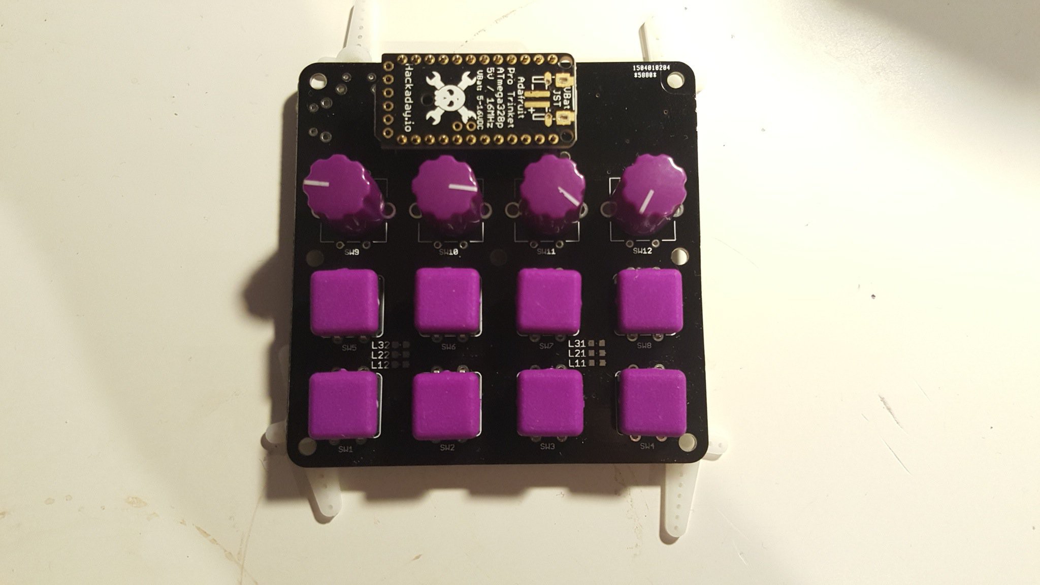
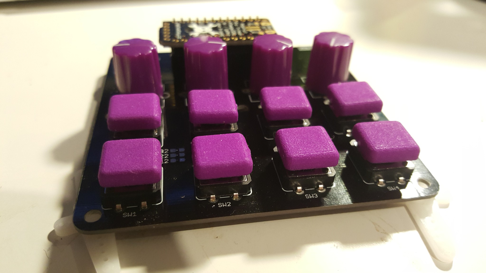
I ordered the parts needed, which was in fact everything except the trinket pro. Looking through eBay I found 12x12 mm tact switches with optional caps on them. Because I like purple, shapeways is able to print purple now and I found this file: http://www.thingiverse.com/thing:493729 that I changed a bit to make the caps bigger (12x12 instead 10x10) I am now in possession of this beauty. It is not soldered yet, but I love the look so far!


Build log

The LEDs came yesterday, so I could finally start building this beauty. I managed to solder the yellow and orange LEDs upside down - so my fix was to solder more LEDs on top of them :D I didn't get the keyboard functions to work though :( Gotta fiddle around with arduino libs and versions again.


Here are the button cap files:

http://www.thingiverse.com/thing:1097850

UPDATE

Thanks to Stefan who send me this link http://www.freebsddiary.org/APC/usb_hid_usages.php I found out that if you use 0xB3 and 0xB4 instead of the 0xB5 and 0xB6 for next and previous song commands, that you don't have to have the window active to switch tracks. At least in my microcosmos, where we also found out that TrinketHidCombo.isConnected() doesn't work.

R8-D8 - a distant relative of R2-D2 | LED projector

2015-10-21 13:14:08

I'm thinking of using a servo that turns a wheel with little pictures in it and put a little LED behind it.

0x03 NTTF - a PSU mod [another UPDATE]

2015-10-21 11:38:52

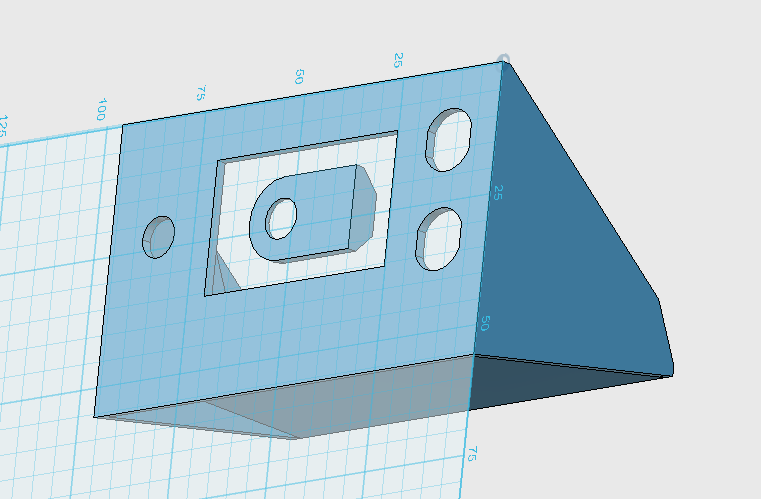
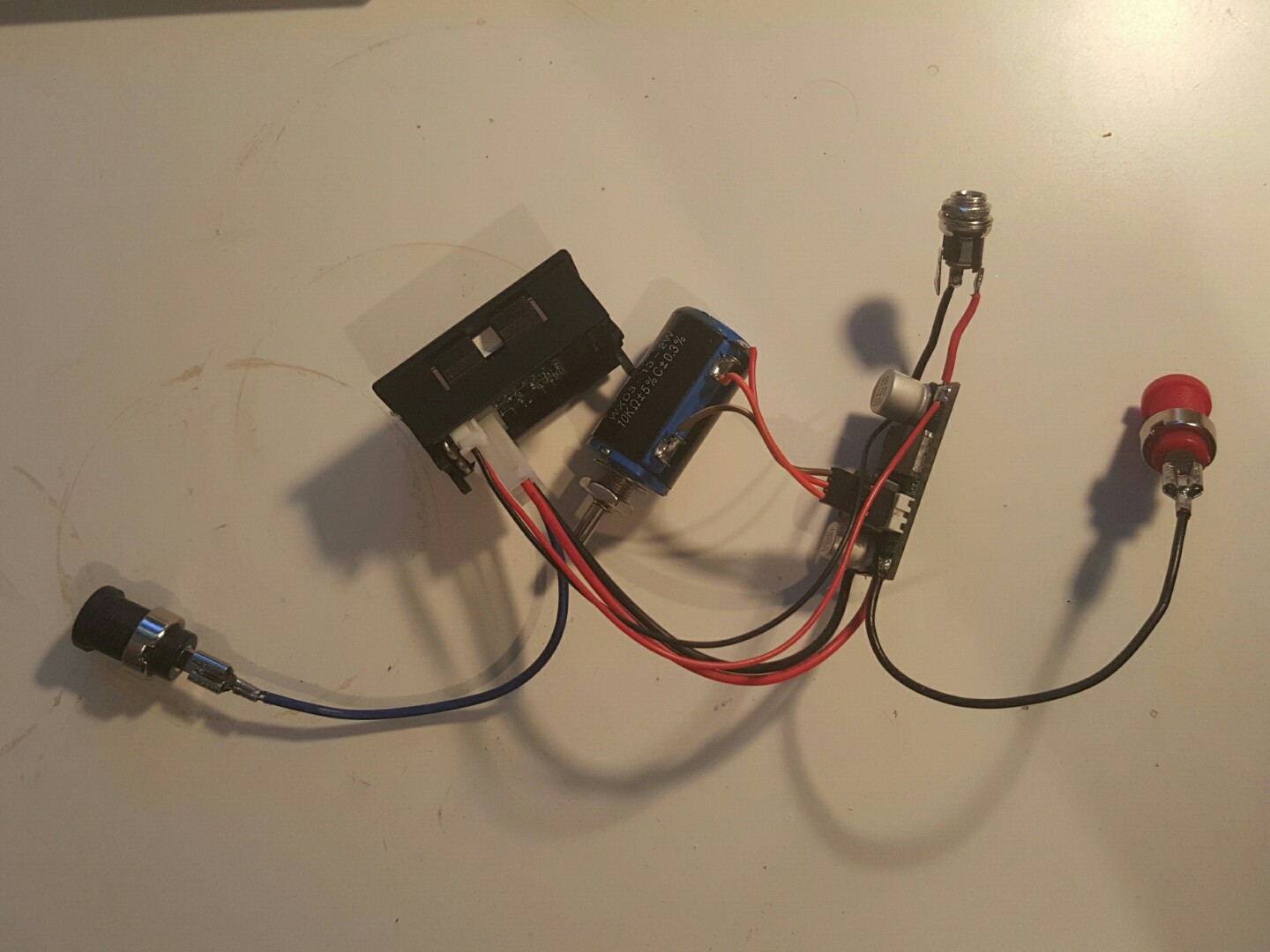
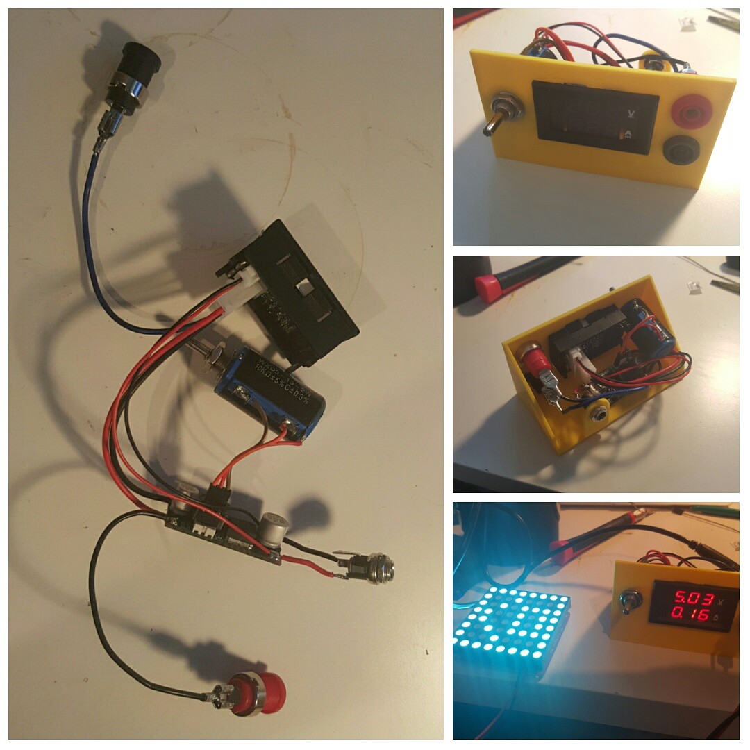
I had to merge my "lab" with my living room to make space for a future flatmate. That means I pull all my projects from their dark, lost corners and places, see their flaws and want to revisit them. Like some of you told me, I was not really going to use it, since it was way too loud, big and other good reasons. Some weeks ago I got some old laptops with 19V PSUs and I thought that with the regulator I bought this would make a good PSU instead. With a ten-turn potentiometer and a 4euro voltage and ampere meter display it could get quite useful.

The wiring was a bit tricky, I will need to write it down or make a sketch for it. There's also a 3D printed case (almost) now!

Johnny IV | blue eye (lids)

2015-10-18 21:20:13

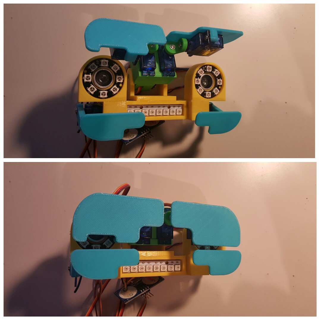
I'm jumping a bit through colors, because I've already used green and yellow and the servos are dark blue etc. ... I want to have him look interesting and colorful!

The mounting for the lower lids will be acetone "welded" on, once they are in the right position.

Printed and glued :)

Heimdall - dumb remote home | 5 SD cards not working?

2015-10-18 00:50:25

this might just be my bad luck, but I really get frustrated with all my raspberry pis... I've ordered some faster cards but seriously suspect my rPi B+ to fail. Is there a number out there on how fast the controller of the PI can read SD cards? Is it worth to grab fancy class 10 cards? Let's see how the new image works.

25MB/s throughput and most likely 22MB/s - class 10 is fine then....

in a nutshell: the newest image of raspbian from september doesn't work well with dd, I always end up with 1byte more at "records in" which made the 2nd partition a no-show.

Now inspecting the SD cards for faults by following this (hopefully) awesome tutorial, using F3.

http://www.broes.nl/2012/08/verify-the-integrity-of-a-flash-sd-card-on-a-mac/

First card output makes me think that my card is fine but my raspberry PI is not :(

wake:AltraMayor-f3-795424c davedarko$ ./f3write /Volumes/UNTITLED/
Free space: 3.74 GB
Creating file 1.h2w ... OK!                        
Creating file 2.h2w ... OK!                        
Creating file 3.h2w ... OK!                        
Creating file 4.h2w ... OK!                        
Free space: 0.00 Byte
Average writing speed: 8.65 MB/s
wake:AltraMayor-f3-795424c davedarko$ ./f3read /Volumes/UNTITLED/
                  SECTORS      ok/corrupted/changed/overwritten
Validating file 1.h2w ... 2097152/        0/      0/      0
Validating file 2.h2w ... 2097152/        0/      0/      0
Validating file 3.h2w ... 2097152/        0/      0/      0
Validating file 4.h2w ... 1556288/        0/      0/      0

  Data OK: 3.74 GB (7847744 sectors)
Data LOST: 0.00 Byte (0 sectors)
	       Corrupted: 0.00 Byte (0 sectors)
	Slightly changed: 0.00 Byte (0 sectors)
	     Overwritten: 0.00 Byte (0 sectors)
Average reading speed: 17.19 MB/s
CompanyClassSize in GBavg. writing speedavg. reading MB/sState
Transcend MMBGF 04GWACA-MG64 [3.74]8.65 MB/s17.19 (16.89)OK
Samsung MB-SS4GVBGBAA-RD44 [3.69]3.08 MB/s17.69 (18.41)OK
Samsung MB-SS4GVBGBAA-RD44 [3.69]3.29 MB/s17.41 (15.64)OK
No brand microSD E408G134968 [7.20]4.31 MB/s17.10 96KB / 192 sectors lost
IntensoN/A4 [3.69]5.62 MB/s11.91 OK
Hama24 [3.67]2.90 MB/s11.84OK
SanDiskN/A2 [1.84]5.46 MB/s9.78OK
Toshiba N/A1 [0.98080]4.42 MB/s12.23OK
Transcend 1016 [14.97]7.55 MB/s16.92 (23.59)OK
Transcend10 (UHS-1)8 []

So only one card shows corrupted sectors. The newest Raspbian image does not like me (dd throws in 1 byte too many). Arch Linux seemed to work and also openELEC. With the new ordered SD cards [16gb class10] and [8gb uhs-1] I have 9 SD cards I can work with. Interesting to see how fast they can actually go and some results are surprising, like the crappy 8GB card and the speedy transcend. I'll try the 16GB tomorrow and also check out the BTRFS Raid1 mode. I might get 2GB for the system and 6GB data storage out of it.

* Seems like the SD card reader integrated in the MacBook Air 2010 is a bit slow, so I started reading the cards again with a Transcend USB 3.0 dongle on the USB 2.0 input. The new data is in brackets.

More links for preventing corrupting SD cards / FS from raspberry PI

http://www.ideaheap.com/2013/07/stopping-sd-card-corruption-on-a-raspberry-pi/

maybe even use the SD card only for the boot fs and use a usb stick for data etc.

https://www.talksharp.com/how-to-prevent-the-raspberry-pi-from-corrupting-sd-cards

"[...] read-only mode. If there's nothing being written to your SD card, it won't get damaged no matter what you do."

http://raspberrypi.stackexchange.com/a/8038

"The best resistance against corruption on a single SD card would be offered by BTRFS in RAID1 mode with automatic scrub run every predefined period of time."

http://unix.stackexchange.com/a/186954

What should I do with SD cards that are corrupted?

Johnny IV | what a mess of wires

2015-10-17 01:03:05

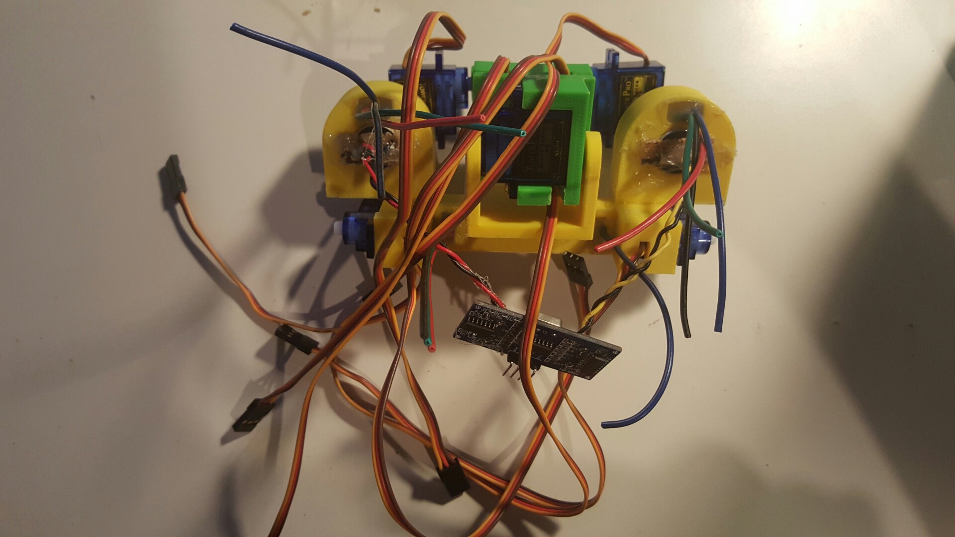
oh dear.... 24 ws2812b LEDs, HC-RS04 and 7 servos!!! I think I'll have to use more than one controller, especially for the ws2812b vs. the servos.

Johnny IV | starting with the eye(s)

2015-10-16 16:10:56

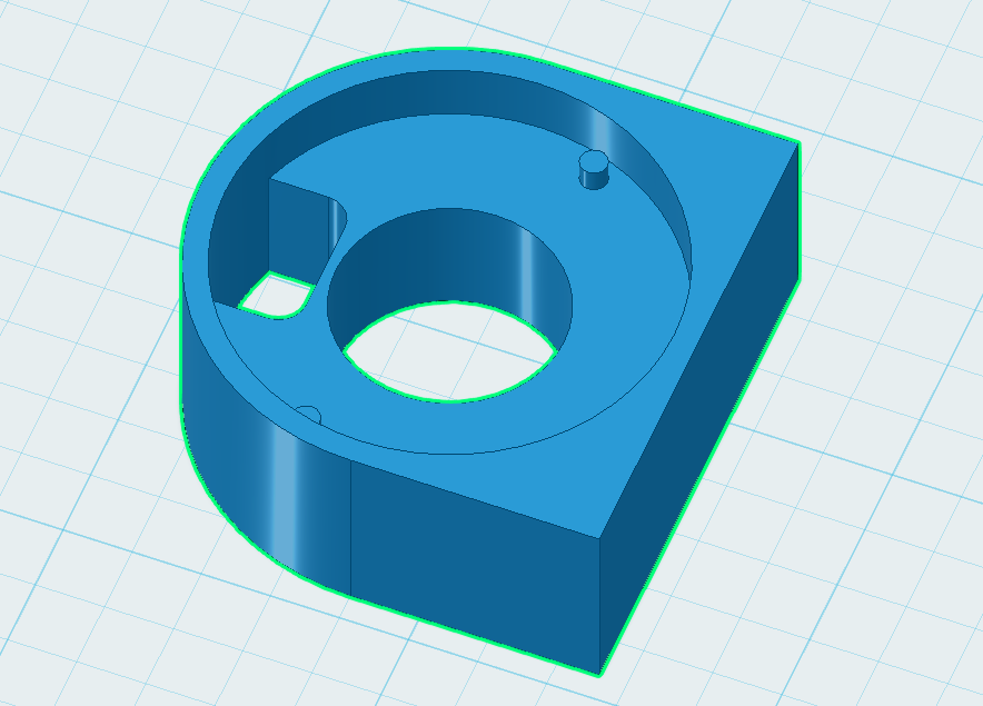
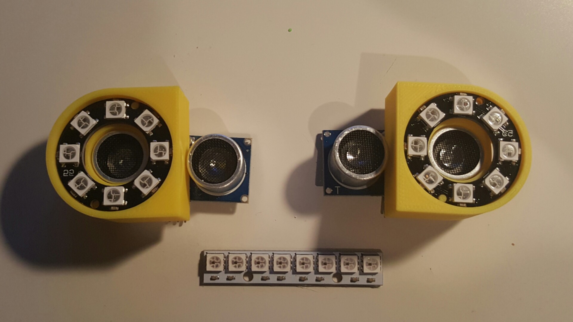
The parts for the eyes are in for a while now, 2x [8leds] neopixel rings and a HC-SR04 module. The rings have some weird 20degrees rotated mounting holes and I plan to desolder the ultra-sonic cans and mount them in the center. This part will be glued onto the other parts, once printed - updates will follow.

So here are the printed parts:

and next up printing is this peace, a mount for the servo eye brows.

Maker Faire Berlin 2015

2015-10-08 00:42:12

[UPDATE] print is done :) Check the bottom of this page.


Still recovering from that weekend. My first maker faire, a "have to", because it was in Berlin, my hometown.

Friday night I was meeting with @WooDWorkeR, @Sophi Kravitz, @Elliot Williams and @al1 at the c-base. Shamefully I have to admit that this was my first trip to the space station based in Berlin, a meet-up place for computer friends, aliens, geeks and nerds and guys with no labels and categories. The tour offered some inspirations for new hacks and we've seen the #warpcore go crazy. Two notable projects that stuck in my head were the little speaker box, that made spherical noises when picking up magnetic fields (telephone amp by a company called micro-electric) and the 4 EL-Wire tube that looked like it was pulsing (no pictures were allowed to be taken, sry). We met other guys that wanted to check out the c-base before going to the maker faire and had a great time.

I think the speaker was based on something like this: http://www.jameco.com/jameco/workshop/diy/magnetic.html


Saturday I've met @al1 at the Ostbahnhof station near the Postbahnhof to go to the maker faire. Greeted by a fire throwing container robot we entered the first floor where some were still preparing their tables. I'm working through the flyers, they aren't in order.


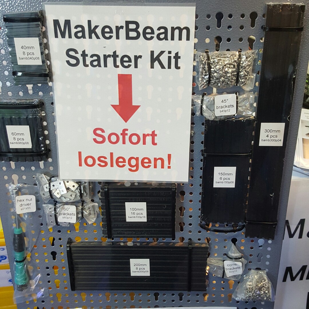
MakerBeam

The first thing that got me interested was the MakerBeam starter kit. There was definitely a lot inside, different length of 1cm x 1cm extruded aluminum profiles with a threaded hole all the way through and multiple connectors to create presentable prototypes.

www.makerbeam.com - www.makerbeam.de
Seedstudio

they brought prototypes of their RePhone and Stickers and buttons and many staff.

https://www.kickstarter.com/projects/seeed/rephone-kit-worlds-first-open-source-and-modular-p

Hartmut Wendt

He brought a din rail case for the raspberry Pi, a mini arcade case and a lot of other little boards that we had a good chat about.

www.hwhardsoft.de

Inspirational projects

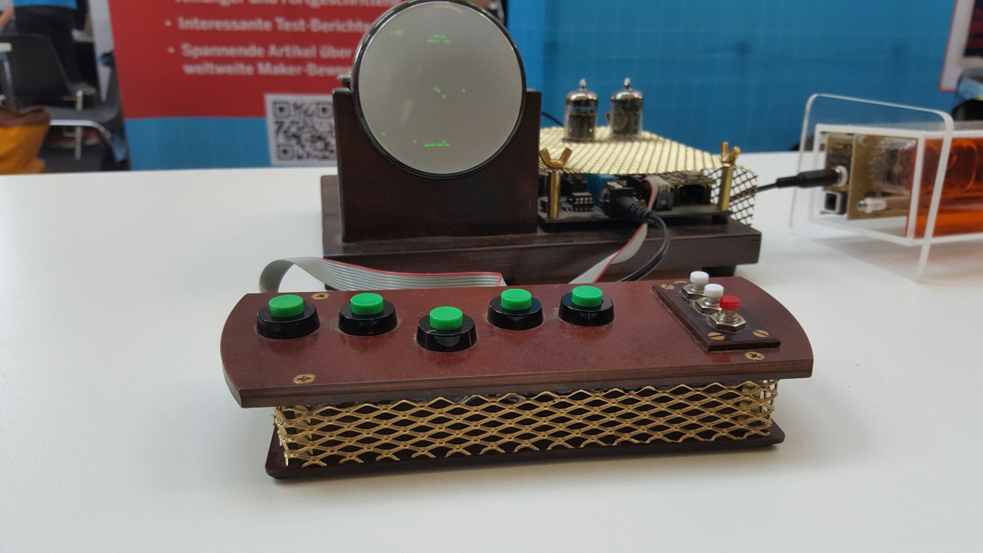
www.hacklace.info - a tiny orange 8x8 matrix driven by an atmega328, arduino compatible - everything in a necklace form factor. I was close to buying one but have so many displays in that size, that I would be angry with my self. Another interesting device was the word clock by www.kellys-finest.de that were designed with common ebay classics like a chead arduino clone, 2 8x8 matrices with max7219 controller and a DS1307 module. And there was this beauty:
Pimoroni

they brought a lot of hats (shields, stacking stuff) for the raspberry PI and they might have thought that I was writing for hackaday.com - I had to wear a HaD shirt. There was a lot of RGB stuff going on!

http://shop.pimoroni.com

Lasercutting and front plates

there were some service sellers that caught my eye. www.formulor.de and www.schaeffer-ag.de were there, and also http://pro.john-steel.com - beautiful interface and good pricing.

---------- more ----------

3D printing

http://i.materialise.com - first price test looks like prices of only 25% percent of shapeways for plastics. MeltWerk had some interesting prints as well, with prices around 75% of shapeways, tested with the same object. If you have a lot of LEGO parts, a browser and not so much time to wait for your 3D prints, you might want to take a look at www.brickify.it - there you can replace easy structures with LEGO parts to save time.

freie Maker

I'm printing myself right now - thanks to the guys from http://freie-maker.de - they brought a 3D scanner and scanned everyone who was interested - should have pulled in my belly :D After scanning a receipt with a link was printed and you have full control over the data. Awesome! We also met @Mario Lukas there and had a little chat.


After seeing the Siegessäule and the vintage computer festival, @al1 and I sank into the couches until the party started. We got our ESP8266 boards out, I brought my #zynthia - sequencer synthesizer and #USB cable tester - @al1 brought his #tiny7 displays. We had some great chats with a couple of guys that were drawn to us by my #RGB 16 Segment LED . We also met @Krzysztof Wrzalka and @Daniel Rojas who brought his two projects, the #Uranium Marble Ring Oscillator and the #Micro Word Clock

@antti.lukats brought some #DIPSY pcbs for everyone (that BGA stuff is tiny!) There was also a guy from the netherlands, who traded a devalued coin for one of my #Lithium Coin Cell charger boards.

I had a great time and exactly one club mate caipirinha too much - should have taken more photos.

Ignore this ESP8266 board | 15 dirtypbcs!

2015-10-07 17:02:06

time for projects... need ideas :D

LED displays on Arduinos - a collection | display stuff

2015-10-07 15:09:57

this slowly turns into a "look what display I've bought this time" project...

I bought 2 5x7 old school vintage LED matrices, called MAN-2A. They are hopefully pin compatible to TIL305 from Texas Instruments. The plan is to make a little time piece with 3x5 digits, so that I would only need two of these displays to get hours and minutes displayed.

http://www.ti.com/lit/ds/sods002/sods002.pdf

RGB 16 Segment LED | Backside

2015-10-04 17:51:43

as requested by @Stefan-Xp

LED displays on Arduinos - a collection | first version boards are in

2015-10-02 00:56:43

and here is the code for the LM75 on board the trinket shield, which finally works.

/*
 March 6, 2014
 Spark Fun Electronics
 Nathan Seidle
 Updates by Joel Bartlett
 
 This code is originally based Dean Reading's Library deanreading@hotmail.com
 http://arduino.cc/playground/Main/SevenSegmentLibrary
 He didn't have a license on it so I hope he doesn't mind me making it public domain: 
 This code is public domain but you buy me a beer if you use this and we meet someday (Beerware license).
 
 This sketch provides a simple counter example for the HP Bubble display from SparkFun.
 https://www.sparkfun.com/products/12710
 
 Pinout for HP Bubble Display:
 1:  Cathode 1
 2:  Anode E
 3:  Anode C
 4:  Cathode 3
 5:  Anode dp
 6:  Cathode 4
 7:  Anode G
 8:  Anode D
 9:  Anode F
 10: Cathode 2
 11: Anode B
 12: Anode A
 */
#include <Wire.h>
#include "SevSeg.h"

//Create an instance of the object.
SevSeg myDisplay;

//Create global variables
unsigned long timer;
int deciSecond = 0;
int f;
void setup()
{
  Wire.begin();
  Serial.begin(9600);
  int displayType = COMMON_CATHODE; //Your display is either common cathode or common anode


  //This pinout is for a bubble dispaly
  //Declare what pins are connected to the GND pins (cathodes)
  int digit1 = 3; //Pin 1
  int digit2 = 4; //Pin 10
  int digit3 = 5; //Pin 4
  int digit4 = 6; //Pin 6

    //Declare what pins are connected to the segments (anodes)
  int segA = 8; //Pin 12
  int segB = 9; //Pin 11
  int segC = 10; //Pin 3
  int segD = 11; //Pin 8
  int segE = 12; //Pin 2
  int segF = 13; //Pin 9
  int segG = 14; //Pin 7
  int segDP= 15; //Pin 5

    int numberOfDigits = 4; //Do you have a 1, 2 or 4 digit display?

  myDisplay.Begin(displayType, numberOfDigits, digit1, digit2, digit3, digit4, segA, segB, segC, segD, segE, segF, segG, segDP);

  myDisplay.SetBrightness(100); //Set the display to 100% brightness level

  // timer = millis();
}

void loop()
{


    char tempString[10]; //Used for sprintf
    sprintf(tempString, "%4d", f); //Convert deciSecond into a string that is right adjusted
    myDisplay.DisplayString(tempString, 4); //(numberToDisplay, decimal point location in binary number [4 means the third digit])

if (millis() - timer >= 1000)
  {
  Wire.write(0x00);  
  Wire.requestFrom(72, 2);  
  
  while(Wire.available()) 
  {
    int8_t msb = Wire.read();
    int8_t lsb = Wire.read();

    // strip one bit of the lsb
    lsb = (lsb & 0x80 ) >> 7; // now lsb = 0 or 1
    f = msb * 10 + 5 * lsb;    
    // add to to form an float
    Serial.println(f,1);
  }
timer = millis();

  }

}

RGB 16 Segment LED | supply power

2015-10-01 21:47:54

I wanted to power my arduino and the wsb2812bs from the same source when running, but didn't want to kill my usb port when programming, so I used some diodes from a rectifier.

RGB 16 Segment LED | Print done

2015-09-29 08:28:30

Black plastic was by choice, I was afraid of color bleeding, if I print in white. I added a coat of primer spray and will later spray it white for highest reflectance. Not sure about the toplayer yet. Might print something with z-glass from zortrax finally.

LED displays on Arduinos - a collection | Arduino Pro Mini - DL1414

2015-09-26 13:10:32

[UPDATE] changed the picture showing the display put on the wrong way to the correct one

So I had this little fellow in my drawers and wasn't really using it because it was so special and also a bit pricey. But yesterday I wanted to check if it still works and I have way to many dev kits and arduinos and stuff, so I just tried it. I looked up the datasheet and checked the pinout - I was so lucky that the arduino pro mini is an excellent candidate for this display, since the power supply pins happened to be on the same position and the rest was IO. Unfortunately I soldered it the other way around. The black, marked with G pin was not pin 7 GND but pin 1. I was able to cross over the supply pins and rotate the data pins for the display. Luckily the highest databits where set in a way that I was able to access the alphabet characters. I have to de- and re-solder it to get numbers too. It's a really smart little device, you have 2 address pins and 7 data pins for ascii code and one write WR pin.

There are at least two versions as it seems, one Siemems DL-1414T and a HP DL-1414.

As always, if anyone knows a better way for getting bits out of bytes to set pins (in an arduino scope) please tell me, this is what I did:

void set_char(byte digit, byte ascii)
{
  digitalWrite(LED_WR, HIGH);  
  digitalWrite(LED_A0, 1 & digit);
  digitalWrite(LED_A1, 1 & digit>>1);
  digitalWrite(LED_D0, 1 & ascii>>0);
  digitalWrite(LED_D1, 1 & ascii>>1);
  digitalWrite(LED_D2, 1 & ascii>>2);
  digitalWrite(LED_D3, 1 & ascii>>3);
  digitalWrite(LED_D4, 1 & ascii>>4);
  digitalWrite(LED_D5, 1 & ascii>>5);
  digitalWrite(LED_D6, 1 & ascii>>6);
  digitalWrite(LED_WR, LOW);
  delay(5);  
  digitalWrite(LED_WR, HIGH);
  delay(5);
}

USB cable tester | Mark III boards are in

2015-09-24 12:17:13

I'll try to toaster oven solder them in the near future.

LED displays on Arduinos - a collection | Arduino Trinket - dual display board

2015-09-21 10:34:16

so I started this wiring mess, and I think for doing this I should reassign the pins first for better connecting. So whenever I remember to print this, I'll update and upload the designs. Just looking at it, I could remove the A6 and A7 pins out of that messy area. This setup would leave me with two analog inputs and a serial connection. I also ordered some IC sockets for the displays, 12pins where hard (read: not) to find, 24 where to special for my taste - so I ordered 8pin IC sockets that are chainable.

After some awesome iterations and mouse clicks of other persons (see comments for credit) - we got this result:

newer 2 / 7 older