LAMEBOY - another ESP12 handheld | back home
2017-08-23 09:52:00
Parts are ordered, some of them over eBay, some of them "locally" at voelkner.de - they're basically conrad.de but with a different pricing ethos and a flatrate for shipping. The almost most expensive part I've ordered there, the TPS2113A for power muxing. Boards are ordered at @oshpark as well and with a little help they might be here even sooner :) Also, first time order at https://www.oshstencils.com/

LAMEBOY - another ESP12 handheld | added SD card slot and C button
2017-08-20 23:26:18
For that I had to move and rewire some stuff, the I2C grove connector now sits on the other side. The SD card found it's place close to the LCD connections and I was able to use the last pin of the ESP for CS of the SD card. Some labels had to be moved as well. The extra C button is more of a troubleshoot / bootloader thing for Gamebuino, but I've added it as some kind of shoulder button anyways. I thought it would make sense to have that SD card and button for supporting the gamebuino games. They won't work with pre-compiled hex files over SD card, since they are compiled for atmega328 chips, but some of them should be easy to install with the Arduino IDE.
I'm not sure why, but at some point I've decided to place the display upside down :D Since they're using adafruit libraries I'll still be able to rotate the display. Nice.
Nice. Last input on the PCF8574 is connected to the SD card connect detection switch pin. Totally overlooked that before. Pretty cool to actually wait and further design the board, instead of rushing orders.

LAMEBOY - another ESP12 handheld | inspirational projects / adaptable platforms
stranger things badge | pretty neat idea from comments
stranger things badge | so it begins
2017-08-19 11:34:08
I've made some screenshots to get started, to anyone interested: watch episode 3 of season 1 to get colors and fonts and wallpaper colors!
hacking a smoke detector | parts considerations
2017-08-19 11:23:00
http://www.ti.com/lit/ds/symlink/tpl5111.pdf 35nA thing that controls pwr converter and shutdown via gpio. only works with up to 5v though, not nine volt battery. so minimal power conversion still would be necessary.
LAMEBOY - another ESP12 handheld | what's next
2017-08-18 01:24:33
This needs a generally tested, breadboarded prototype, or at least it should. I've added 2.2mm drill holes where I could for later case designs to screw on, but I'm not sure about them. A beast to layout and probably more to solder! Seems to make sense to get a stencil for the first time.
- The attiny has some transistors for the RGB backlight now
- I've added a grove connector for other I2C modules
- moved some parts around
- removed the tCream pads off of my AVR pads

LAMEBOY - another ESP12 handheld | PCF8574 - wait what?
2017-08-16 00:52:16
Although I had my run on some designs using this chip, I had to check the datasheet again and noticed something weird. Everyones project I've seen just uses a button that pulls the pin to ground. But what can we observe here on P5? A pull-up resistor of 100kOhms pulls up the input, until you push a switch that connects it to even more pull-ups? I should sleep and tomorrow remove my pull-up stuff from the board.
https://www.mikrocontroller.net/articles/Port-Expander_PCF8574
#D1 Mini X-Pad Shield
#HariFun#133 More I/O Madness
#Portable Raspberry PI Zero

LAMEBOY - another ESP12 handheld | audio research
link drop for modding/repairing/hacking stuff | lab stuff
2017-08-11 10:51:17
I'll be in America from mid September to mid October, afterwards I'll buy some new lab furniture :)
Ikea Billy 0.8m width on 3.4m
4 billys 54euros each
216 total
zynthia - sequencer synthesizer | Rev2 boards are here
2017-08-10 22:26:10
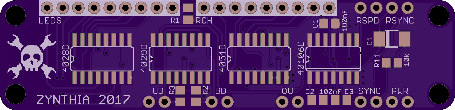
I still have to update the OSHpark Board, there are some minor label changes (if it works at all, that is :D ):
C2 is a 10nF cap
C1 is a10uF cap
So this board should have all the bells and whistles it can:
- 8 LEDs
- 8 Tone knobs for pitch
- up/ down switch for the counter
- binary / decimal switch for the counter (count to 8 / 10)
- Synced oscillator switchable
- Speed for the counter potentiometer
- Sync / Pitch knob

K.I.T.T. - KNIGHT RIDER badge/brooch | already had to sell the first assembled one
2017-08-10 22:23:20
And for the money I've bought some more boards, this time black pcbs from dirtypcbs.com though - sorry to every other vendor, but please add eagle brd file support :D Anyway, I wanted to have some black K.I.T.T.s with red LEDs as well.
link drop for modding/repairing/hacking stuff | Leap Frog Music Player hack
2017-08-04 17:45:32
LCD Controller replacement
- 64x32 lcd with 96 pins
- ht1650 holtek as an optional driver
scrapped, I have #LAMEBOY - another ESP12 handheld and neon pink 3D printing filament now, I don't need this anymore and it's already gone :D
K.I.T.T. - KNIGHT RIDER badge/brooch | Boards are here :)
2017-08-02 18:53:14

Ha! Fail...
2017-07-21 20:37:57
So I thought that my LiPo Chargers in form of 4056 modules are all weird, broken and not powerful enough, until I've noticed that my UNI-T UT61E multimeter isn't calibrated anymore(?)! Stupid me also calibrated other stuff like my Power Supply made from a buck down converter and a notebook PSU using that meter. I also thought my R8D8 power bank was off big time and the batteries were done, because I've continuously measured 3.8V on each cell with that multimeter... meh. Cheap multimeter now tells me I'm stupid. meh.
Anyone any tips for voltage references? Or how I can recalibrate voltage without another multimeter?
[update] I've seem to programmed all my attiny13 for #FLUX capacitor trinket with 13V instead of 12V, thanks to my multimeter... meh. but hey, they work.
link drop for modding/repairing/hacking stuff | my 858D soldering station
FLUX capacitor trinket | So I've made myself an AVR resetter then
2017-07-16 20:37:38
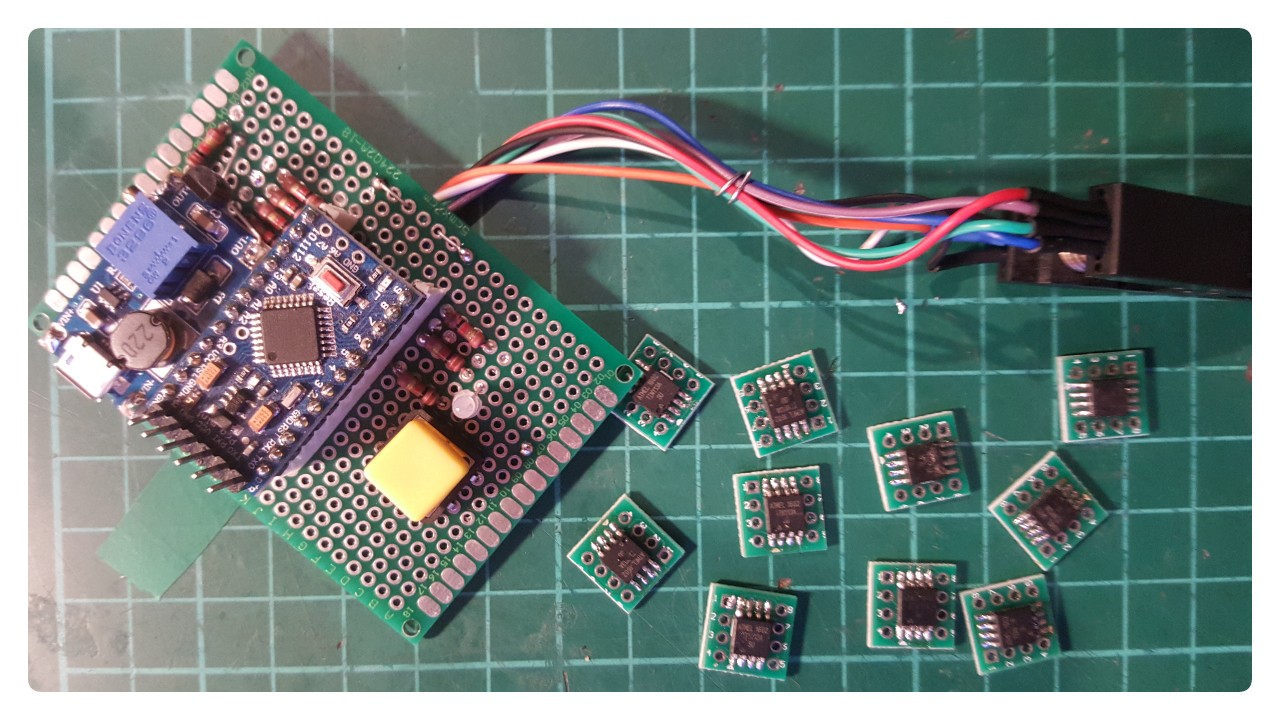
to fix almost all my tiny13a's I had to build this, but it definitely fixed all 10 boards :) for the tinies you don't need any parallel connections, so it's basically SPI + 12V on reset. I've hooked up a boost converter, added a button and "some" LEDs (bicolor), worked them in the code and now basically have a "power on and fix" stand alone fuse resetter for soic Attinies. That's not highly specialised at all. BUT IT WORKS AND THEY WORK! Now I need to clean up my desk.
http://www.engbedded.com/fusecalc/
https://arduinodiy.wordpress.com/2015/05/16/high-voltage-programmingunbricking-for-attiny/
#define RST 13
#define SCI 12
#define SDO 11
#define SII 10
#define SDI 9
#define VCC 8
#define BUTTON 3
#define LED_RED 7
#define LED_GRN 5
#define HFUSE 0x747C
#define LFUSE 0x646C
#define EFUSE 0x666E
#define ATTINY13 0x9007
#define ATTINY24 0x910B
#define ATTINY25 0x9108
#define ATTINY44 0x9207
#define ATTINY45 0x9206
#define ATTINY84 0x930C
#define ATTINY85 0x930B
void setup() {
pinMode(BUTTON, INPUT_PULLUP);
pinMode(LED_GRN, OUTPUT);
pinMode(LED_RED, OUTPUT);
pinMode(VCC, OUTPUT);
pinMode(RST, OUTPUT);
pinMode(SDI, OUTPUT);
pinMode(SII, OUTPUT);
pinMode(SCI, OUTPUT);
pinMode(SDO, OUTPUT);
digitalWrite(RST, HIGH);
Serial.begin(19200);
}
void loop() {
digitalWrite(LED_GRN, HIGH);
digitalWrite(LED_RED, LOW);
if (digitalRead(BUTTON) == LOW)
{
digitalWrite(LED_GRN, LOW);
digitalWrite(LED_RED, HIGH);
pinMode(SDO, OUTPUT);
digitalWrite(SDI, LOW);
digitalWrite(SII, LOW);
digitalWrite(SDO, LOW);
digitalWrite(RST, HIGH);
digitalWrite(VCC, HIGH);
delayMicroseconds(20);
digitalWrite(RST, LOW);
delayMicroseconds(10);
pinMode(SDO, INPUT);
delayMicroseconds(300);
unsigned int sig = readSignature();
Serial.print("Signature is: ");
Serial.println(sig, HEX);
readFuses();
if (sig == ATTINY13) {
writeFuse(LFUSE, 0x6A);
writeFuse(HFUSE, 0xFF);
} else if (sig == ATTINY24 || sig == ATTINY44 || sig == ATTINY84 ||
sig == ATTINY25 || sig == ATTINY45 || sig == ATTINY85) {
writeFuse(LFUSE, 0x62);
writeFuse(HFUSE, 0xDF);
writeFuse(EFUSE, 0xFF);
}
readFuses();
digitalWrite(SCI, LOW);
digitalWrite(VCC, LOW);
digitalWrite(RST, HIGH);
delay(1000);
}
}
byte shiftOut (byte val1, byte val2) {
int inBits = 0;
while (!digitalRead(SDO))
;
unsigned int dout = (unsigned int) val1 << 2;
unsigned int iout = (unsigned int) val2 << 2;
for (int ii = 10; ii >= 0; ii--) {
digitalWrite(SDI, !!(dout & (1 << ii)));
digitalWrite(SII, !!(iout & (1 << ii)));
inBits <<= 1; inBits |= digitalRead(SDO);
digitalWrite(SCI, HIGH);
digitalWrite(SCI, LOW);
}
return inBits >> 2;
}
void writeFuse (unsigned int fuse, byte val) {
shiftOut(0x40, 0x4C);
shiftOut( val, 0x2C);
shiftOut(0x00, (byte) (fuse >> 8));
shiftOut(0x00, (byte) fuse);
}
void readFuses () {
byte val;
shiftOut(0x04, 0x4C);
shiftOut(0x00, 0x68);
val = shiftOut(0x00, 0x6C);
Serial.print("LFuse ");
Serial.print(val, HEX);
shiftOut(0x04, 0x4C);
shiftOut(0x00, 0x7A);
val = shiftOut(0x00, 0x7E);
Serial.print(", HFuse: ");
Serial.print(val, HEX);
shiftOut(0x04, 0x4C);
shiftOut(0x00, 0x6A);
val = shiftOut(0x00, 0x6E);
Serial.print(", EFuse: ");
Serial.println(val, HEX);
}
unsigned int readSignature () {
unsigned int sig = 0;
byte val;
for (int ii = 1; ii < 3; ii++) {
shiftOut(0x08, 0x4C);
shiftOut( ii, 0x0C);
shiftOut(0x00, 0x68);
val = shiftOut(0x00, 0x6C);
sig = (sig << 8) + val;
}
return sig;
}zynthia - sequencer synthesizer | Gaaaaah ... it was too close to midnight!
2017-07-13 23:33:39
Thanks to @al1 I'm now aware that I've mixed up the GND and VCC symbols from the schematics of @Elliot Williams :D So now it's corrected and everything looks even cleaner! Definitely will sleep on ordering this one (hopefully al1 will have another look, just to be sure) :D I'm not looking forward to the boards arrival - straight to the totem of failure, I guess.

FLUX capacitor trinket | Attiny13 woes
2017-07-13 22:01:20
Okay, here we go:
Left OSHPark board: attiny13a SSU - working
Right OSHPark board: attiny45 - working
all 10 green boards: attiny13a SU - not working
Red board: attiny13a SSU - not working (but same badge as left OP board - weird)
USB cable tester: attiny13a SSU - working
small OSHPark board: attiny13a SSU - no idea
out of 15 attiny13a boards I know that two are working :( meh. At first I thought The smaller tinies are definitely fake, but the datasheet says they're a possibility.

zynthia - sequencer synthesizer | smd version
2017-07-11 23:42:29
I came around to design an SMD version of the perfboard version :)
On board is:
- 8ch LED port
- 8ch potentiometer port
- counting up/down switch
- octade (binary) / decade switch
- synced pitch switch and potentiometer
- speed potentiometer