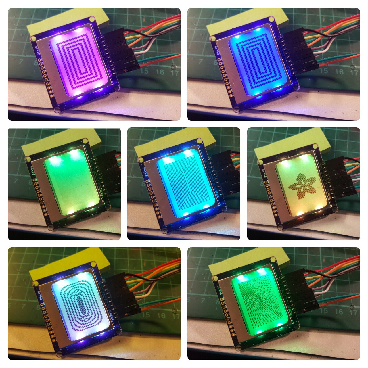
Nokia 3310 / 5110 display board | one board is soldered
2017-01-26 00:07:40
Notes:
- definitely order 0.8mm boards (I failed because it was after midnight... )
- pins for display can be shortened by shield -> edit footprint!
- 5V stuff is confusing! I only considered it for getting more "bang" for the buck
- next version should have Attiny13 for I2C RGB control
- maybe add an ESP12 foot print
- play with MQTT (red alert / temperature stuff)
- also RGB pinout is not correct!
- resistors for colors are not in the same order and values must be corrected
- ESP12 analogWrite has 10bit resolution!
433MHz MQTT remote | Is it alright to say DaveCAD?
2017-01-21 21:45:08
the button matrix

433MHz MQTT remote | known problems
2017-01-21 18:10:36
I have no idea what I did, but GPIO16 behaves weird. There is a transistor that allows me to toggle the cols with one pin. PIN 16 "OFF" weirdly jumps between HIGH and LOW, but I neglect that because you can achieve the desired state by just pressing the button longer.
Like with many of my projects there is no backside yet, but this is so much better than having the pure PCB flying around.
An external antenna could be handy, at least a 17cm wire or so.
Game Boy Cartridge plus Programmer | DFU made me jump around
2017-01-17 02:14:02
This board is way out of my Arduino comfort zone... so I'm writing down what I've managed to learn or am able to estimate. I was trying to get this code running http://www.ssalewski.de/AT90USB_firmware.html.en - and the way it was given to upload was via a program called dfu_programmer, that is probably best installed via homebrew for mac (my given machine).
brew install dfu_programmer
I tried and tried and couldn't figure out what I'm doing (wrong) until I've read someone writing in a forum that in a case of a flashed program there wouldn't be the generic dfu bootloader anymore. Luckily Atmel gives you the DFU hex files on the download page. Here is the datasheet for the bootloader: http://www.atmel.com/Images/doc7618.pdf
To activate the bootloader you have to have pulled down the HWE pin when releasing the RST pin, a state that my board is constantly set to, since I've copied the teensy design not knowing "better". At this point I'm not sure if this is working well with the bootloader, but I have my concerns since I can't flash anything, but see the devices as "
AT90USB128 DFU" in my USB list.
I have to bodge some buttons and resistor / capacitor thingies together, like in the Hardware Guide of the AT90USBKEY http://www.atmel.com/Images/doc7627.pdf
The following link [http://www.engbedded.com/fusecalc/] is still pretty useful for getting the values for the fuse bytes to set the HWBE fuse and the Boot Reset fuse. They seem to be important. Also weird:
sudo dfu-programmer at90usb1287 getfuse
target doesn't support fuse set operation.
And this is my log of failure, when trying to flash the Atmega1287. Another thing to do is looking up the Halfkey bootloader on the teensy.
dfu-programmer at90usb1287 flash main.hex --debug 100
     target: at90usb1287
    chip_id: 0x2ffb
  vendor_id: 0x03eb
    command: flash
      quiet: false
      debug: 100
device_type: AVR
------ command specific below ------
   validate: true
   hex file: main.hex

atmel.c:1153: atmel_flash( 0x7fff5d5b1b40, 0x7fff5d5b1a08, false, false )
intel_hex.c:673: intel_flash_prep_buffer( 0x7fff5d5b1a08 )
atmel.c:1193: Flash available from 0x0 to 0x1DFFF (64kB p. 0 to 1), 0x1E000 bytes.
atmel.c:1197: Data start @ 0x0: 64kB p 0; 128B p 0x0 + 0x0 offset.
atmel.c:1201: Data end @ 0x17F: 64kB p 0; 128B p 0x2 + 0x7F offset.
atmel.c:1206: Totals: 0x180 bytes, 3 128B pages, 1 64kB byte pages.
atmel.c:819: atmel_blank_check( 0x7fff5d5b1b40, 0x00000000, 0x0000017F )
atmel.c:927: atmel_select_memory_unit( 0x7fff5d5b1b40, 0 )
atmel.c:941: Ignore Select Memory Unit for non GRP_AVR32 device.
Checking memory from 0x0 to 0x17F...
atmel.c:986: atmel_select_page( 0x7fff5d5b1b40, 0 )
atmel.c:1000: Selecting page 0, address 0x0.
atmel.c:752: __atmel_blank_page_check( 0x7fff5d5b1b40, 0x00000000, 0x0000017f )
atmel.c:784: Flash region from 0x0 to 0x17F is blank.
atmel.c:862: Flash blank from 0x0 to 0x17F.
Empty.
atmel.c:927: atmel_select_memory_unit( 0x7fff5d5b1b40, 0 )
atmel.c:941: Ignore Select Memory Unit for non GRP_AVR32 device.
Programming 0x180 bytes...
atmel.c:986: atmel_select_page( 0x7fff5d5b1b40, 0 )
atmel.c:1000: Selecting page 0, address 0x0.
atmel.c:1289: Program data block: 0x0 to 0x17F (p. 0), 0x180 bytes.
atmel.c:1424: __atmel_flash_block( 0x7fff5d5b1b40, 0x7fff5d5b1a08, false )
atmel.c:1386: atmel_flash_populate_header( 0x7fff5d5b14a0, 0x0, 0x17F, false )
atmel.c:1340: atmel_flash_populate_footer( 0x7fff5d5b14a0, 0x7fff5d5b1640, 65535, 65535, 65535 )
atmel.c:1485: atmel_flash: flash data dfu_download failed.
atmel.c:1487: Expected message length of 432, got -9.
atmel.c:1292: Error flashing the block: err -2.
ERROR
Memory write error, use debug for more info.
commands.c:514: Error writing memory data. (err -4)
PCB word clock | some documentation added
2017-01-15 14:46:17
Since someone on twitter pointed out that the project documentation is an epicfail, I felt compelled to edit the details and add informations on charlieplexing and the general idea. I first was a bit annoyed, but mostly because the entity was right :) I tend to not document my projects very well, mostly because it's easier to write about it afterwards and laziness. Now it feels more complete though.
hacking a smoke detector | vulcan needed, must be good in logic.
2017-01-14 01:54:39
01:49 am - no boards ordered.
When breadboarding around I've noticed that I made a fatal mistake in that I've connected every GND signal, where there should have been two GNDs that will only be connected when the MOSFET is turned on by the 4001 NOR gate RS Flipflop. So at this point the boards can only be used as breakout boards.

I still have to test the transistor circuit, I think I have it the other way around. I'll test that tomorrow to be fully sure this time. I think I have to pull it low with a resistor and use a PNP instead to reset the flip flop.

PCB word clock | boards are ordered
2017-01-12 16:19:40
So for science I've also added the german layout and ordered this one on 0.8mm boards.
fail: I bought a fake teensy 2++
2017-01-04 17:40:21
I have to rant a bit, because I bought stuff cheap and it byte back. So I'm mad, but it's my fault.
This is what I bought:
http://www.ebay.de/itm/Teensy-2-0-USB-AVR-Development-Board-ISP-U-Disk-AT90USB1286-for-Arduino-TE502-/272272218585?hash=item3f64b059d9:g:ILIAAOSwqBJXXbQI
There's a total f'up with the wiring of the power lines, the fix can be found in the image "wI40iZV.jpg" of this thread, that I'm very happy to have found. I'm not embedding the pic because I haven't asked for permission and don't want to create an account there.
http://www.ps3hax.net/archive/index.php/t-97227.html
They also managed to deliver it with an AMS1117, where the center pin is Vout and the center pin on the board is ground! So this is what I ended up with:
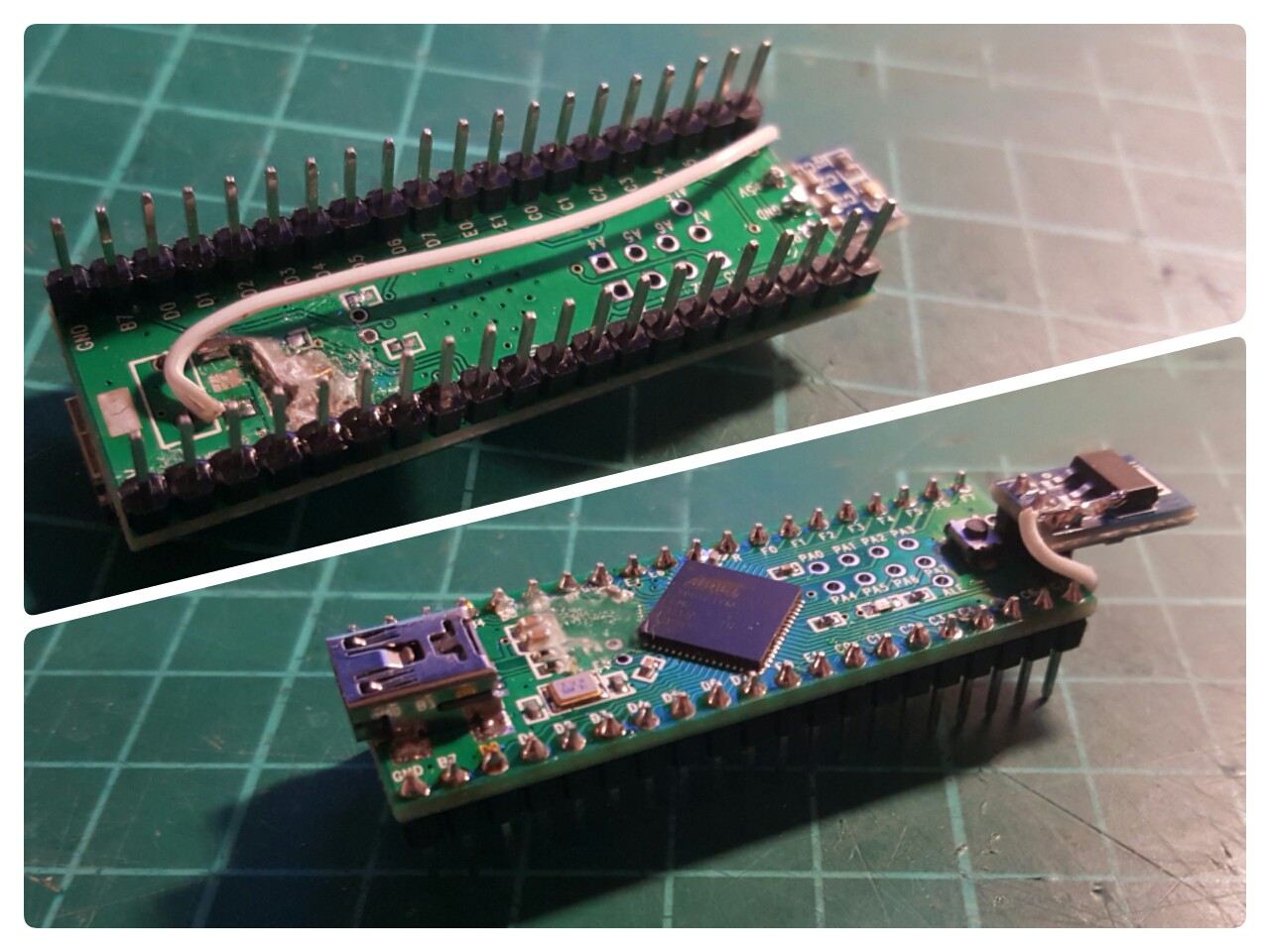
5 bugs saved vs. 5 hours dev time - damn. Lesson learned! Don't be too cheap! Respect the OP.
hacking a smoke detector | already revisioning
2017-01-02 19:26:08
I thought about using "dual 2 input nor gates" for the flip-flop circuit, because of space and maybe I could add a battery monitoring circuit to it then. But those aren't as cheap as 4001 chips.
D'oh!
I think I messed up two things:
- the signals are not right - the NOR gate outputs should be the other way around
- I have no transistor on the ESP to change the state of the flip flop
I guess I have to wait on the parts and test... meh. Wasted day
hacking a smoke detector | not only youtube inspirations
2017-01-02 13:07:13
Amazon Dash button seems to work in the same way (button activates power supply, device shuts down afterwards)
This video (and also projects from @Radomir Dopieralski) inspired me to use the Wemos form factor
hacking a smoke detector | design choice: Wemos shield
2017-01-02 12:48:10
I thought a bit about the design and decided to make it compatible to the Wemos D1 board, but also put a minimal "FTDI + ESP12" configuration on there, so the maker can decide what he will build.
Since GPIO15 is pulled low anyway and I'm able to use it - why not make it the latch off pin.


Portable Raspberry PI Zero | I2C on an Attiny85
2017-01-01 22:47:50
So I thought I would just add the Attiny85 family to the boards by adding the following link to my Additional Boards Manager URLs in my Arduino 1.6.9 IDE and get away with it and use the wire library to hack a little LED PWM backlight controller together. But since that didn't work for the tone() lib on the #Nyan Board , why would it here?
https://raw.githubusercontent.com/damellis/attiny/ide-1.6.x-boards-manager/package_damellis_attiny_index.json
So I then look around and find this library on GitHub https://github.com/rambo/TinyWire and with it's help I was able to whip together the LED controller! The idea here is that the pin 3 is connected to the PI and when toggled will write the PWM to pin 4. This PWM value can be set via I2C address 0x04.
#define I2C_SLAVE_ADDRESS 0x4
#include <TinyWireS.h>
int pwm_value = 127;
#ifndef TWI_RX_BUFFER_SIZE
#define TWI_RX_BUFFER_SIZE ( 16 )
#endif
void setup() {
TinyWireS.begin(I2C_SLAVE_ADDRESS);
TinyWireS.onReceive(receiveEvent);
pinMode(3, INPUT);
pinMode(4, OUTPUT);
}
void loop() {
TinyWireS_stop_check();
writeLed();
}
void writeLed()
{
if (digitalRead(3) == HIGH)
{
analogWrite(4, pwm_value);
}
else
{
digitalWrite(4, LOW);
}
}
void receiveEvent(uint8_t howMany)
{
if (howMany < 1)
{
return;
}
if (howMany > TWI_RX_BUFFER_SIZE)
{
return;
}
TinyWireS.receive();
howMany--;
if (!howMany)
{
return;
}
while(howMany--)
{
pwm_value = TinyWireS.receive();
}
}