all years
202620242023202220212020201920182017201620152014
2211152313307215210213462
newer 7 / 8 older

Game Boy Cartridge plus Programmer | Just throwing an idea out

2017-02-27 15:24:05

I think it might be possible to have the ESP8266 inside a cartridge, with an Atmega16A faking to be a dual port (SPI + parallel BUS) SRAM and the ESP8266 faking to be a memory bank controller. This way I could grab data from the web, put it into "RAM" and read it out with the game boy. This way I could also get rid of the dongle ESP idea. Some protocols would have to be written and thought out. Feeling very yoda-ish today. Gotta eat sth.


Research update

Game Boy Cartridge plus Programmer | multi bank roms are working too

2017-02-26 21:07:15

I played around with the code and a Game Boy Camera module, but it all was very weird. I was able to read the header once, and only after I unsucessfully read parts of RAM I was able to read the header again. I'm testing cartridges with RAM modules and different memory bank controllers. I should write down everything I learned about the Game Boy at some point.


Game Title: METROID2

Cartridge Type: 3 - MBC1+RAM+BATTERY

ROM Size: 3 - 256KByte (16 banks)

RAM Size: 2 - 8 Kbytes (1 Bank)


Porygon V2 - but not the evolution of Porygon | legs and tail have servo horn mountings

2017-02-26 21:03:36

off to the printer ... so many great projects in the contest and I want that oscilloscope - but I can probably forget about that already :D head is another topic, soonish, we're all on a deadline.

hey my fellow shermans... wanna buy stuff?

2017-02-25 18:15:39

I'm currently selling things on eBay, just throwing out what would collect dust otherwise. There's currently no international shipping planned, but if someone reaaaaally needs stuff from my oh so small list, tell me and we can find a solution. I hope it's not too bold to advertise something like this, but hey - it has to pay the hobby ;) Should I sell something else, while I'm on it? Any PCBs or Kits?


http://www.ebay.de/usr/davedarkocom

Game Boy Cartridge plus Programmer | woot :3 - Tetris is mine!!!!

2017-02-25 01:10:59

[UPDATE] Ha! Nevermind, they are the same, Hex Editor told me that I was missing a "00" - now everything "checks out". Checksum pun.


I've made it! I'm far from sharing anything, but I finally managed to read AND store a full game! Everything is based on the speedtest for the serial interface over USB and another file storing sample for C. I had to fiddle around with buffer sizes and remove a string in a hexfile editor, but it counts, the came works :) I get 4 times the same checksum for 4 cartridges, but somehow I get a different checksum for a downloaded ROM, and the files look very different.

- Anyways, probably best to go to bed now :)

Game Boy Cartridge plus Programmer | Oops, I did it again

2017-02-24 10:55:58

[UPDATE] silkscreen and the upside-down side of things

An after midnight board, how classic [don't] [just] [don't]. I could have breadboarded this as well first, to check if it actually works. Damn. Now I'm hesitant to reorder, I should try it first. - Wait, what am I talking about?


This is a shield for the Wemos D1 mini, that features a TXB104D, a level-shifter with auto detection for direction. The picture seen here is the corrected version, after ordering the failed PCB. By accident I've mirrored the game boy connecter, because I tried to rotate it in my head. This version has numbered pins, to make it more easy to check. Otherwise I'm pretty proud of it. I can still use it as a breakout board for the TXB104D and check if the connector gets a clean cutout, even use the Wemos D1 mini to talk to 5V stuff.


There are "rumours" that the ESP is 5V tolerant and the Game Boy might be happy with 3V3 volts of the ESP, but I'm not eager to try. By rumours I mean, I thought I have read that somewhere.


Here is that ear worm you're trying to get rid off. Gremlins and ear worms, classic Dave.


Game Boy Cartridge plus Programmer | This slowly turns into an everything game boy project

2017-02-23 14:26:20

I just received my Game Boy Pocket in Classic colors, a japan only release - and I'm in love :3 yellow backlight and bivert mod are on its way. The center one is an old silver game boy where I removed the silver, swapped the display and put in shapeway printed purple buttons. The yellow one is my first GBP.

Game Boy Cartridge plus Programmer | muahaha, I cheated :)

2017-02-21 02:07:23

So since the Teensy++ 2.0 bootloader is not available and I'm not feeling comfortable to learn all the bells and whistles of USB communications I was looking for other options. Googling "at90usb1287 arduino" I found this https://github.com/mattairtech/ArduinoCore-avr - I chose the AT90USB1287 deliberately because of the native USB and fast speeds and way too many IOs to work with, and got it to work with my board :)

https://www.mattairtech.com/index.php/development-boards/mt-db-u6.html


I basically had to add the link to the json file to my boards manager library in th Arduino IDE and download the bootloader from their page (burn bootloader from arduino didn't set the fuses right?). I started with turning lights on and off, because as always blink is a good point to start. I noticed that my register setting skills were non existing, because I always mix up port direction and pin setting, but in the end I found the right way to set the ports and blink the lights. Reading the data port was also easy, after testing and finding out that the JTAG on pins F4-F7 weren't deactivated like the mattairtech folks promised.


Anyway... boom. Single ROM bank cartridges, fear me! Here's the verbose header dump of one of my TETRIS cartridges. Bank switching and writing cartridges to be next. It's fast. Off to bed.

100: 0 - 
101: C3 - �
102: 50 - P
103: 1 - 
104: CE - �
105: ED - �
106: 66 - f
107: 66 - f
108: CC - �
109: D - 

10A: 0 - 
10B: B - 
10C: 3 - 
10D: 73 - s
10E: 0 - 
10F: 83 - �
110: 0 - 
111: C - 
112: 0 - 
113: D - 

114: 0 - 
115: 8 - 
116: 11 - 
117: 1F - 
118: 88 - �
119: 89 - �
11A: 0 - 
11B: E - 
11C: DC - �
11D: CC - �
11E: 6E - n
11F: E6 - �
120: DD - �
121: DD - �
122: D9 - �
123: 99 - �
124: BB - �
125: BB - �
126: 67 - g
127: 63 - c
128: 6E - n
129: E - 
12A: EC - �
12B: CC - �
12C: DD - �
12D: DC - �
12E: 99 - �
12F: 9F - �
130: BB - �
131: B9 - �
132: 33 - 3
133: 3E - >
134: 54 - T
135: 45 - E
136: 54 - T
137: 52 - R
138: 49 - I
139: 53 - S
13A: 0 - 
13B: 0 - 
13C: 0 - 
13D: 0 - 
13E: 0 - 
13F: 0 - 
140: 0 - 
141: 0 - 
142: 0 - 
143: 0 - 
144: 0 - 
145: 0 - 
146: 0 - 
147: 0 - 
148: 0 - 
149: 0 - 
14A: 0 - 
14B: 1 - 
14C: 1 - 
14D: A - 

14E: 16 - 
14F: BF - �

PCB word clock | Version One :)

2017-02-17 03:06:21

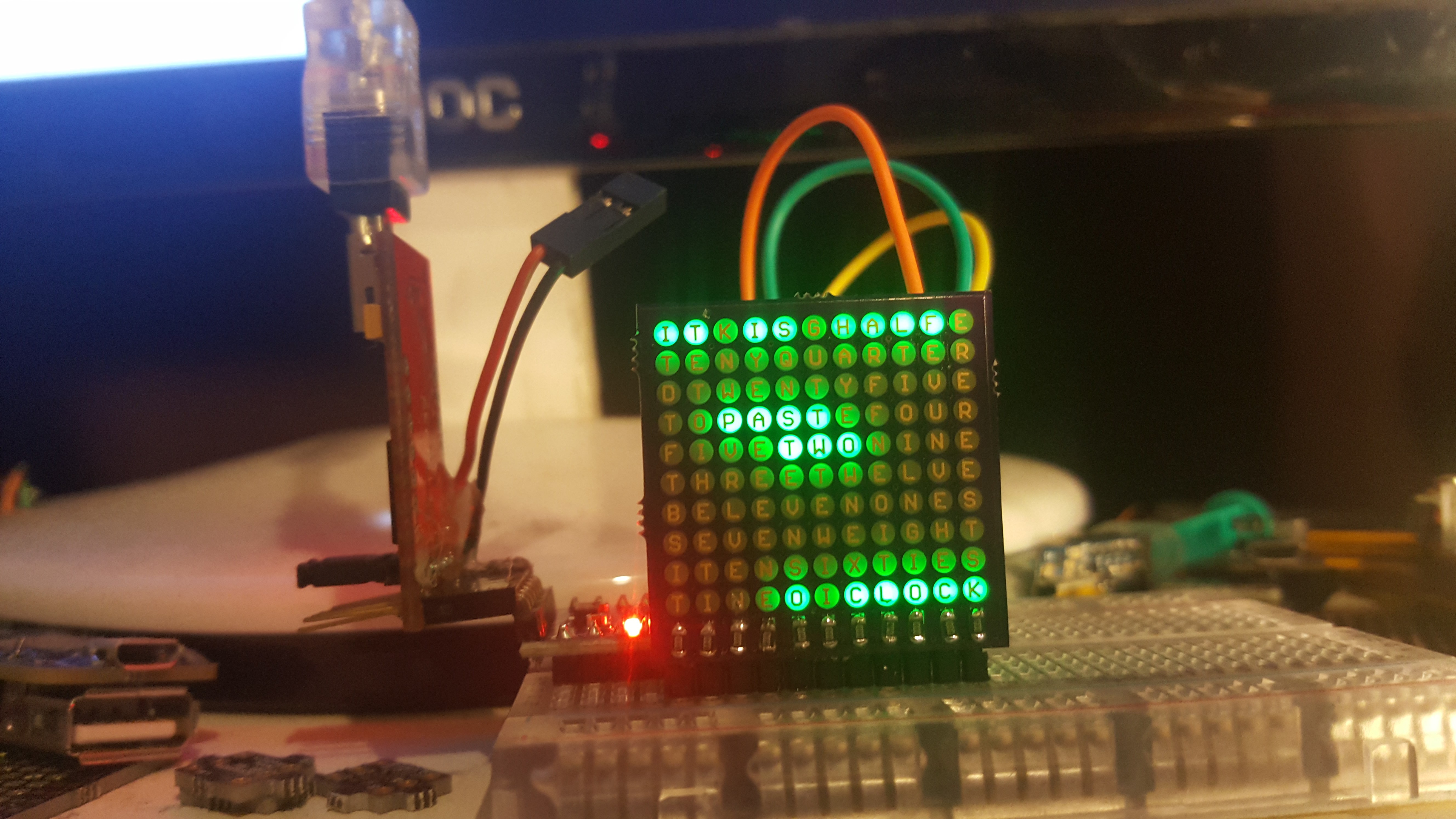
Update fun fact: analyzing a charlie plexed matrix for bugs is so much easier when the LEDs are upside down - because of the markings :)


I finally got my LEDs and took the time to hand solder a PCB :) it bleeds a bit in the picture, but in real life it's quite good. The code so far is only a mock up, but there is scanning and matrix stuff involved already.
#include <avr/pgmspace.h>

const int leds[]  = {2,3,4,5,6,7,8,9,10,11,12,13};

const int matrix[10][11][2]  = {
  {  {1, 0},  {0, 1},  {0, 2},  {0, 3},  {0, 4},  {0, 5},  {0, 6},  {0, 7},  {0, 8},  {0, 9}, {0, 10} }, // 0
  {  {2, 0},  {2, 1},  {1, 2},  {1, 3},  {1, 4},  {1, 5},  {1, 6},  {1, 7},  {1, 8},  {1, 9}, {1, 10} }, // 1
  {  {3, 0},  {3, 1},  {3, 2},  {2, 3},  {2, 4},  {2, 5},  {2, 6},  {2, 7},  {2, 8},  {2, 9}, {2, 10} }, // 2
  {  {4, 0},  {4, 1},  {4, 2},  {4, 3},  {3, 4},  {3, 5},  {3, 6},  {3, 7},  {3, 8},  {3, 9}, {3, 10} }, // 3
  {  {5, 0},  {5, 1},  {5, 2},  {5, 3},  {5, 4},  {4, 5},  {4, 6},  {4, 7},  {4, 8},  {4, 9}, {4, 10} }, // 4
  {  {6, 0},  {6, 1},  {6, 2},  {6, 3},  {6, 4},  {6, 5},  {5, 6},  {5, 7},  {5, 8},  {5, 9}, {5, 10} }, // 5
  {  {7, 0},  {7, 1},  {7, 2},  {7, 3},  {7, 4},  {7, 5},  {7, 6},  {6, 7},  {6, 8},  {6, 9}, {6, 10} }, // 6
  {  {8, 0},  {8, 1},  {8, 2},  {8, 3},  {8, 4},  {8, 5},  {8, 6},  {8, 7},  {7, 8},  {7, 9}, {7, 10} }, // 7
  {  {9, 0},  {9, 1},  {9, 2},  {9, 3},  {9, 4},  {9, 5},  {9, 6},  {9, 7},  {9, 8},  {8, 9}, {8, 10} }, // 8
  { {10, 0}, {10, 1}, {10, 2}, {10, 3}, {10, 4}, {10, 5}, {10, 6}, {10, 7}, {10, 8}, {10, 9}, {9, 10} } // 9
};

const boolean img [10][11] = {
  { true,  true, false,  true,  true, false,  true,  true,  true,  true, false},
  {false, false, false, false, false, false, false, false, false, false, false},
  {false, false, false, false, false, false, false, false, false, false, false},
  {false, false,  true,  true,  true,  true, false, false, false, false, false},
  {false, false, false, false,  true,  true,  true, false, false, false, false},
  {false, false, false, false, false, false, false, false, false, false, false},
  {false, false, false, false, false, false, false, false, false, false, false},
  {false, false, false, false, false, false, false, false, false, false, false},
  {false, false, false, false, false, false, false, false, false, false, false},
  {false, false, false, false,  true, false,  true,  true,  true,  true,  true},
};

void setup()  { }

void loop() {
    for (int y=0; y<10; y++) 
    {
      for (int x=0; x<11; x++) 
      {
        if (img[y][x]) charlie_matrix (x, y);
    }
  }
}

void charlie_matrix (int x, int y)
{
   int cx = matrix[y][x][0]; 
   int cy = matrix[y][x][1]; 
  
  digitalWrite(leds[cx], LOW);
  pinMode(leds[cx], OUTPUT);
  digitalWrite(leds[cy], HIGH);
  pinMode(leds[cy], OUTPUT);
  delayMicroseconds(65);

  pinMode(leds[cx], INPUT);
  digitalWrite(leds[cx], LOW);
  pinMode(leds[cy], INPUT);
  digitalWrite(leds[cy], LOW);
  
  delayMicroseconds(5);
}

Porygon V2 - but not the evolution of Porygon | head hollowed out, eyes prepared for flux leds

2017-02-16 09:51:13

Porygon V2 - but not the evolution of Porygon | spend more time with the model

2017-02-15 12:15:51

The cavity should be big enough for the electronics. I cut off a bit of the tail. first body print was pretty good. I had to make some adjustments for the servo cables.

I still need to:

Porygon V2 - but not the evolution of Porygon | skeleton work

2017-02-13 22:55:48

I've done some 3D sketching, servos are the classic SG90 servos, I still need to fit LEDs, an Arduino/ESP and a battery pack in there.

Game Boy Cartridge plus Programmer | a creature of habit might learn something to stay in comfort zone

2017-02-12 23:06:23

What a fantastic title for a link drop

I might want to program the programmer from arduino at some point

Game Boy Cartridge plus Programmer | DFU second round

2017-02-12 20:53:02

Once again I've put on the DFU USB bootloader onto the AVR AT90USB1287, after reading the bootloader PDF without any disctractions :D There I read that the chips need a full erase before you can program them over DFU. Did that. Than I also found out that I have to start the program I've burned ... oh well :) works! Awesome :) - now the actual programming can start :D

# If nothing works, try it with the force :D
sudo dfu-programmer at90usb1287 erase --force

# "Hexe" means witch, this is not witchcraft
sudo dfu-programmer at90usb1287 flash main.hex

# the bootreset fuse starts the bootloader after the reset
# so you won't start your program but restart the bootloader 
sudo dfu-programmer launch --no-reset

RGB LED Oscilloscope | Mildly annoying results

2017-02-11 13:33:24

I should have tested it before, first the kit themself and then the forrest mims version. The matrix is all soldered up and the kits are soldered like I've interpreted it so far.

At this point I cant tell what I've captured there, I'm having my thumb on signal ground to produce some jitter.


Some thoughts

blinking things | 3 little boards - blinky stuff

2017-02-10 20:37:20

Wemos 2812B moaaaar LEDs shield

After seeing RGBW LEDs on the Adafruit stream I quickly went on Aliexpress to buy some and then designed a Wemos D1 shield for them, just not with only one LED.


SMD LED bargraph for breadboards (with Resistors)

A classic, but I was in the mood to design it.


RGB LEDs charlie-plexed pinout

This is basically the layout of one column of a 4x4x4 RGB LED cube...

RGB LED Oscilloscope | 3mm mono colored prototype

2017-02-10 12:19:27

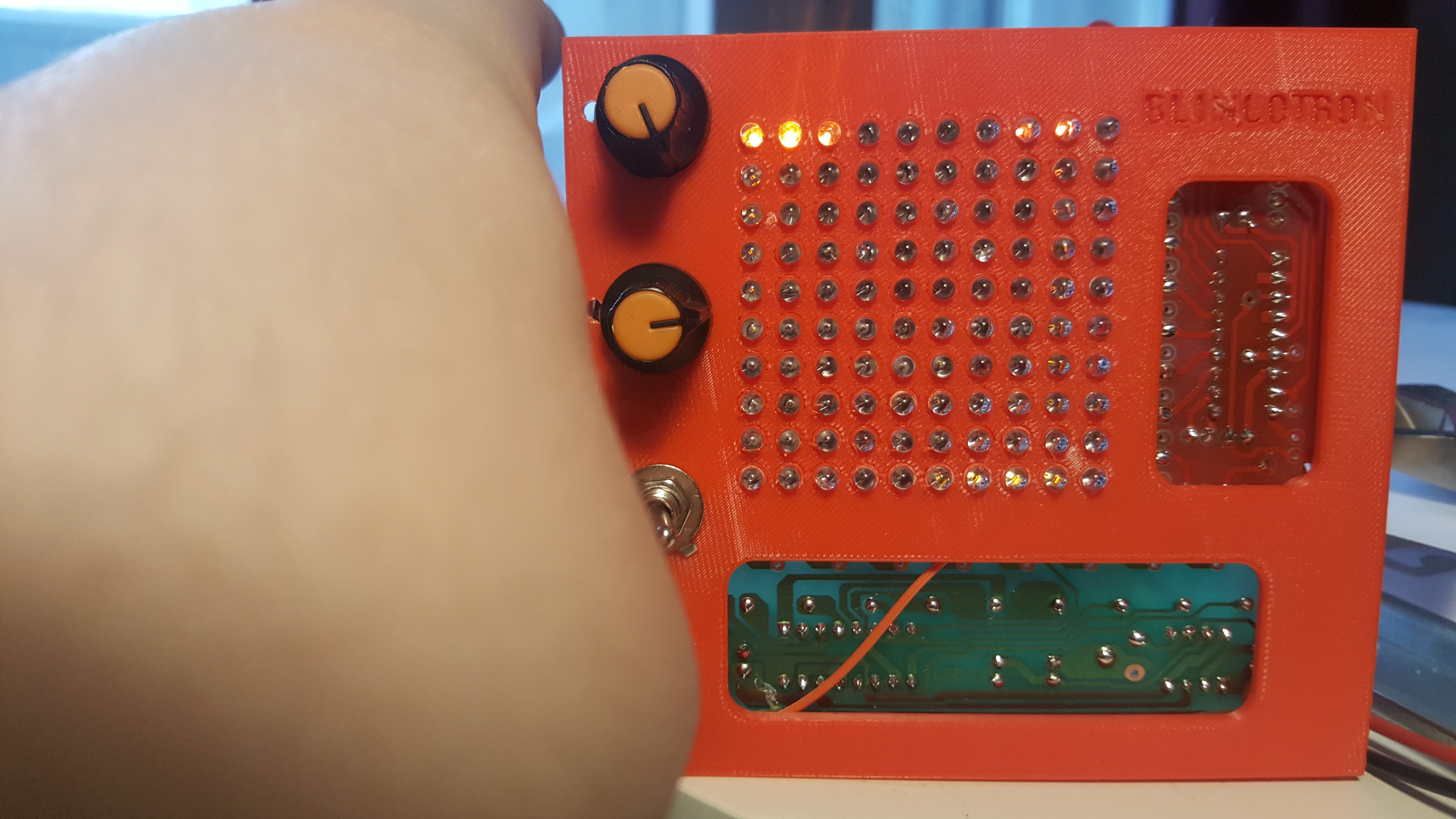
Yesterday I thought I could 3D print a little LED holder to solder up a 3mm LED 10x10 matrix, where with that I could kit bash a mono prototype together - well, that escalated quickly. Out came the "blincotron". Since the front side looked a bit offset and boring, I've also added windows for the colorful backside of the pcbs to show. There are 2 potentiometer wholes and one for a switch, to manipulate "vertical gain", "horizontal sweep" and "freee running vs. triggered sweep". Still missing is a whole for the input signal (of course....) and a good spot for the 4011.

RGB LED Oscilloscope | shopping time

2017-02-06 12:47:49

My favorite time of a project cycle!

partspriceamounttotal
100pcs common anode CA RGB LEDs 3.41 EUR13.41 EUR
CD4017 NE555 LED chaser board 1.15 EUR11.15 EUR
LM3915 "funny" diy kit board1.50 EUR34.50 EUR
Total9.06 EUR

Thanks to current political events that makes: 9.73 USD

With a little creative air wiring this will make a lovely solder Sunday :)

zynthia - sequencer synthesizer | a little upgrade

2017-02-05 00:23:23

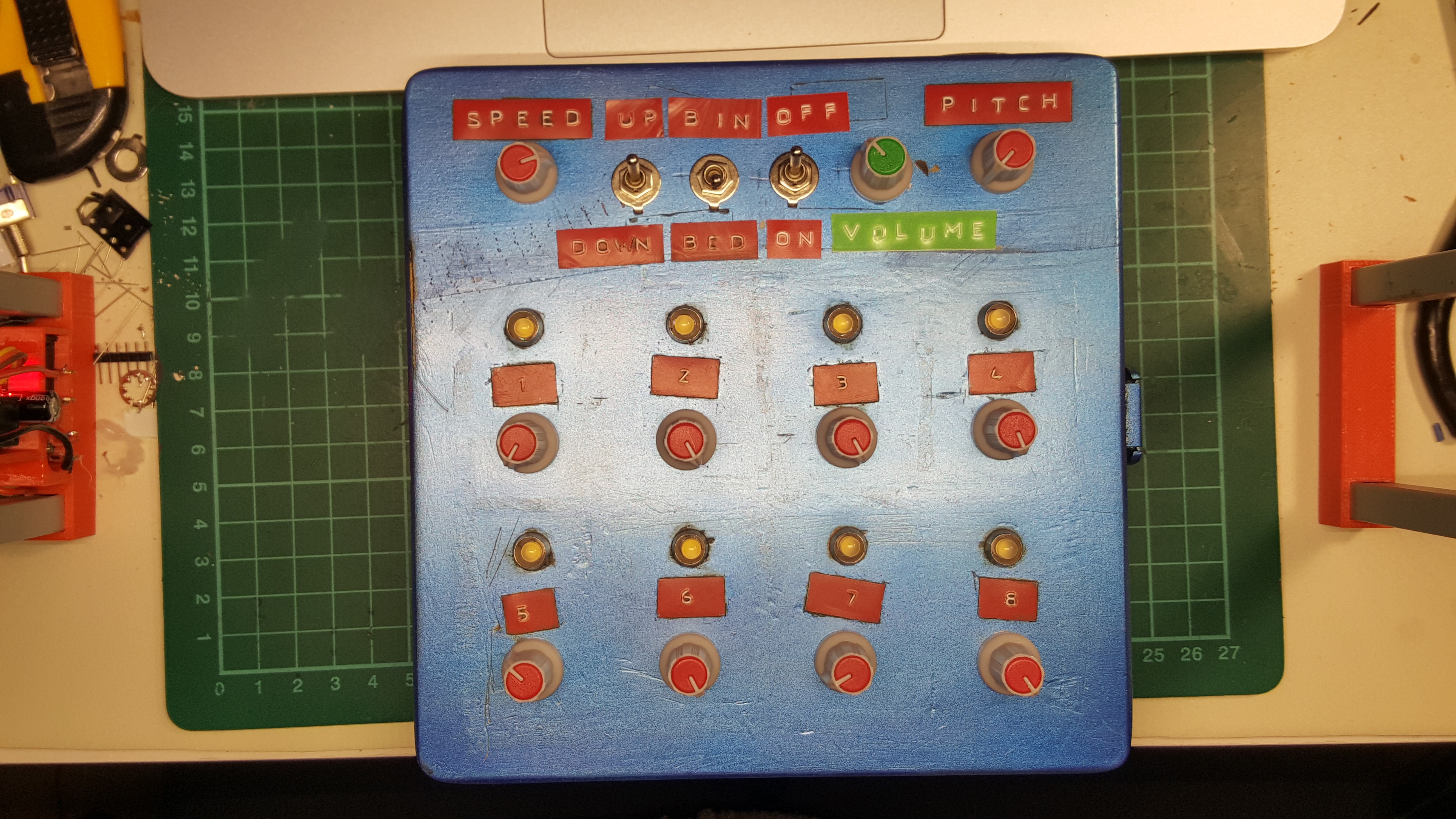
I've bought one of those cheap LM386 DIY kits on eBay and upgraded Zynthia to be fully stand alone. I only had 10 red caps for the resistors, so I took green instead and a dymo label, the last switch is now the power switch :) I also mixed up one power cable and without checking I've almost killed a battery by shorting it :D

http://www.ebay.de/itm/272323639604?_trksid=p2057872.m2749.l2649&ssPageName=STRK:MEBIDX:IT

Nokia 3310 / 5110 display board | should I Tindie / eBay this?

2017-01-27 14:41:45

I'm seriously considering to fix the minor problems, make another batch and sell them. Here are some thoughts and questions.

Design considerations

Pricing

could be around 10 Euros and still have a good margin.

newer 7 / 8 older