WIFI Game Boy Cartridge | getting closer to a layout
2017-04-19 22:54:44
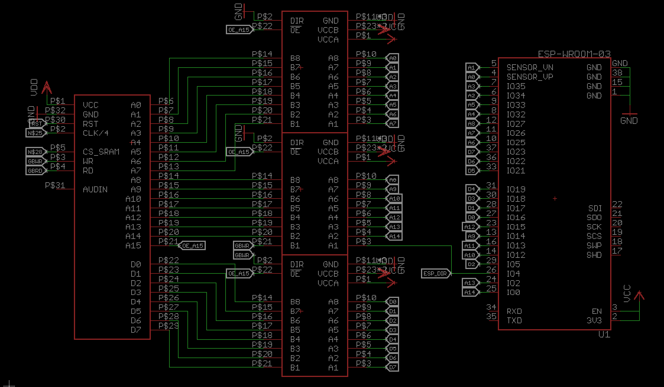
I was able to drop a 74LVC8T245 level converter and connect the address pins. A15 on the Game Boy is basically the "chip select" for the ROM / cartridge, when pulled down, since the address space of the 32kb is 0x0000 to 0x7FFF. SO I use that for the output enable pin on the lvl converter.
The Game Boy write pin will define the direction of the data pins lvl converter. The address lines will be pulled low, meaning the direction is always B->A. I use the pin that was previously the A15 pin to tell the ESP the direction of the communication.
A0-A3 are connected to input only pins of the ESP. Not unlike the ESP12F there are some pins that are connected to the SPI flash on the module and shall not be connected otherwise.
So far I only have the RX and TX pin free, but I consider to have the RST line on a transistor - maybe I need to hold the game boy in a reset state for a while, for the ESP32 to boot up and set all pins.
Not on the picture is the current power supply. I'm a bit worried about the two AAA / LR03 batteries in my Game Boy pocket, they're not that powerful in general and with the LED backlight it's not better. Drawing from the 5V switch mode to convert to up to 250mA will be a challenge. I might need to add a LiPo and/or some tantalum capacitors to make it work.
WIFI Game Boy Cartridge | stuff ordered
2017-04-19 09:44:24
so before I make a PCB and order it for a lot of money (that's almost true, I have a coupon), I thought I buy parts for a lot of money, but hey - there's more money to collect now [http://hackaday.com/2017/04/18/up-up-up-2k-more-seed-funding-for-projects-that-matter/].
Some almost breadboard friendly 74LVC8T245 were ordered, although they have their pinheaders upside down. [http://www.ebay.de/itm/302193394421]
I have an ESP32 basic adapter board (dual row headers, no power converting), but I'll wait on the breadboard adapter I've ordered, with all the bells and whistles. (full disclosure, I wrote balls the first time)
With that the 20bugs on that project are almost spend :) but it's good to have it. There are also two #Hornbill in the making, but they arrive much later.
WIFI Game Boy Cartridge | esp32 acting as cartridge
2017-04-18 16:46:53
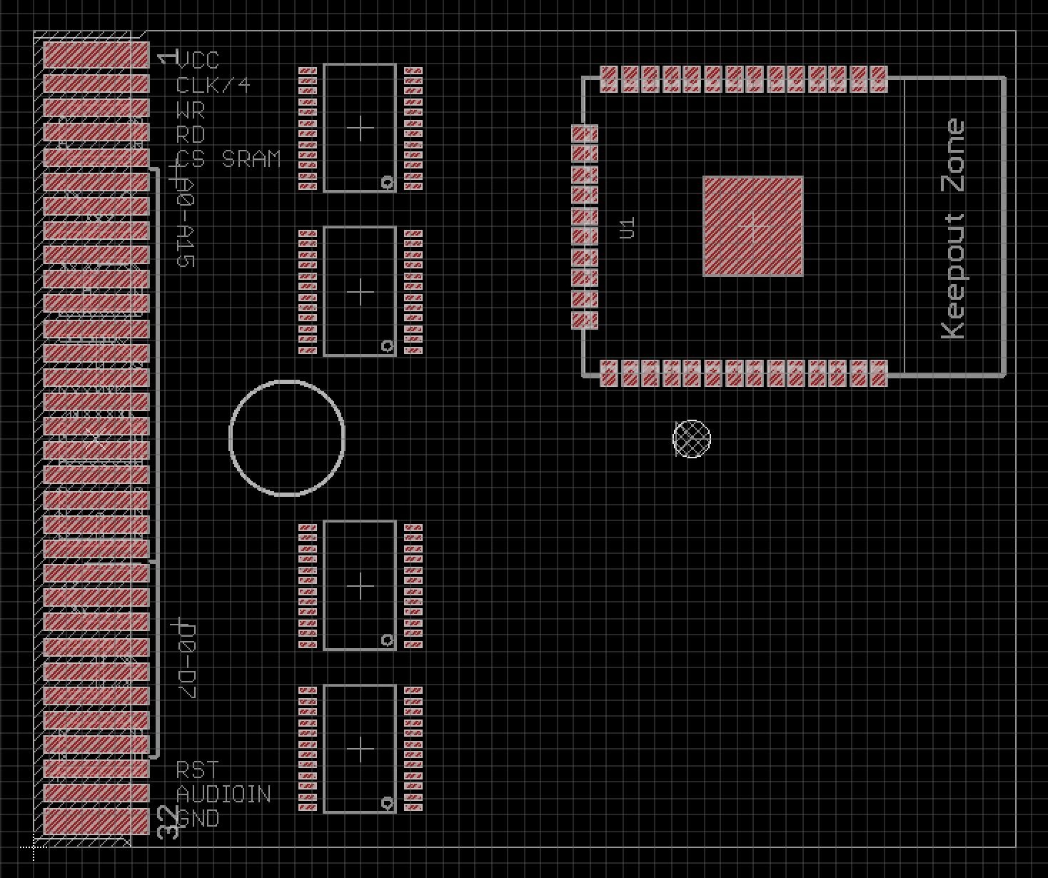
i would need 4 SN74LVC245
- 2 for the 16bit address port
- 1 for the controls
- 1 for data, where the direction could be controlled by the read/write pins
Game Boy Cartridge plus Programmer | Proud moment :)
2017-04-16 14:36:21
finally! So I took the cartridge code and just placed it as an array on the at90usb1287. Teh, after writing, then reading to the eeprom I got it to work :)

blinking things | HT16K33 board for 11x7 LED matrix
2017-04-15 18:04:49
I recently bought a cool 11x7 matrix, that is just great to display 4 3x5 digits and I want to control it with the well supported HT16K33 - so here's a not so beautiful and highly convoluted board for that.


WIFI Game Boy Cartridge | PINs and timings
2017-04-13 14:39:26
there are still some issues left to solve on my #Game Boy Cartridge plus Programmer project, that I want to solve this weekend [proud moment]. After that I will pin down the hardware. maybe an atmega32 would be an option as well for the "SRAM" part, but a faster atsamd21 seems more reasonable.
https://www.insidegadgets.com/2011/04/23/emulating-the-nintendo-logo-on-the-gameboy/
this tells me I should be safe with an ESP12 as an MBC1 controller. I need 8 pins for the cartridge and 3 for SPI to control the AVR. I don't need the data pins to be connected, I can use the AVR for that.
The next thing would be the SRAM. This will be handled by an ATSAMD21 / adafruit feather M0 (logger) board. It has 20 pins available, so I won't be able to fake an 8k SRAM. That would take 13 pins for address, 8 data and 3 control pins. Since I also need to connect SPI, I have 17 pins left. I need 11 pins for data and control, that makes 64 bytes fake SRAM.
Maybe I can use the ESP to make the AVR read the data pins and switch banks via SPI later.
Game Boy Cartridge plus Programmer | writing is off after some bytes
2017-04-08 23:58:14
So the Nintendo Logo is on the cartridge - I can see that because it scrolls down, but after the "bading" it stays black. A quick check comparing the original to the dump shows this:

Game Boy Cartridge plus Programmer | hackaday logo ROM
2017-04-06 00:03:23
http://www.chrisantonellis.com/gameboy/gbtdg/
with the help of this little website I was able to create a little Game Boy ROM, that displays the hackaday jolly wrencher. You can find the code and rom in the file sections. I tried to upload the files and write it to the cartridge, but had no success so far. Not sure what's going on, but I'm too tired to try to find out.
You only need to add the following code to the generated C file, depending on that your file was called something like HaDlogo.bmp - otherwise you have to rename stuff.
#include <gb/gb.h>
#include <stdio.h>

void main()
{
  set_bkg_data(0,255,HaDlogo_tile_data);
  VBK_REG = 1;
  set_bkg_tiles(0,0,20,18,HaDlogo_map_data);
  SHOW_BKG;
  DISPLAY_ON;
}
WIFI Game Boy Cartridge | looking for parts etc.
2017-04-02 23:02:03
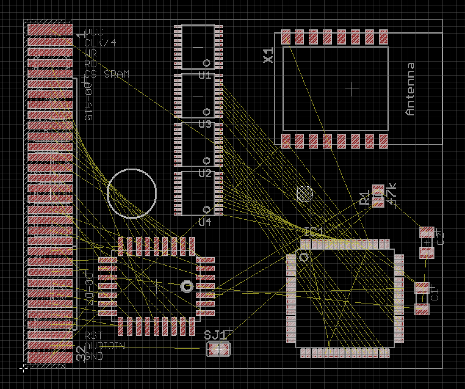
Starting from my #Game Boy Cartridge plus Programmer designs, I tried to add some parts and lay them out, to get a feeling for it. I still need power conversion and am thinking about adding a separate power source for the ESP side.
To Recap the Idea:
- the ESP12 will behave like a Memory Bank Controller (MBC) that handles the bus traffic, meaning who is asked for and who will talk (I still hope I have enough pins left)
- the AVR (AT90USB1287) will be connected via SPI to the ESP12 if it is to slow, I could just ask it twice or three times for the value to make sure I have the right data
- the ESP would know that the AVR has to be enabled, instead of the EEPROM, so it needs to be able to enable or disable them
- I need some level-shifting on the board from 3.3V to 5V and the ESP is quite power hungry, so maybe I'll add lots of caps or another battery
LCsoft Mini Board CY7C68013A in Sigrok on Mac
2017-03-07 12:00:24
Four Euros for a 16 channel, 24MHz logic analyzer is a pretty good investment. At least that's what I thought when I read this article on hackaday.com in 2012. It talks about the LCSOFT mini board being a clone of a Saleae 8 Channel logic analyzer, but with the help of the open source software sigrok it can be much more. Sigrok itself is a command line interface only program, but together with pulseview I think you will have the same experience as with the Saleae devices + software.
You just have to make it work first, especially when you're on a Mac. I've written a nightly rant the other day, but here I'm trying to compress the essentials to make it work.
First you need to have homebrew [https://brew.sh/] installed. If you do, you need to follow the "unstable" install route - doesn't sound comforting, more on: https://sigrok.org/wiki/Mac_OS_X
$ brew tap rene-dev/sigrok
$ brew install python3
$ brew install
$ brew install
$ brew install
$ brew install
$ brew install
Whenever pulseview(/sigrok) is opened, the firmware get's written onto the Cypress CY7C68013A (FX2LP) chip. For that you need to download the pre-built firmware files from here http://sigrok.org/download/binary/sigrok-firmware-fx2lafw/ and move them to the folder.
/usr/local/share/sigrok-firmware/
The other stuff I ranted about in here is just me trying to make fxload work, a tool you (probably) don't need for that.
burn firmware CY7C68013A on a Mac [nightly brain dump]
2017-03-06 02:50:43
Warning: Only read if you want to flash and use the CY7C68013A module with sigrok on a mac!
It all started six years ago with this article, written by @Mike Szczys: http://hackaday.com/2011/12/15/saleae-logic-analyzer-knockoff-hacking/
Once upon a time I bought a - CY7C68013A dev board [https://sigrok.org/wiki/Lcsoft_Mini_Board], because I read that one could use this shiny cheap thing with the fancy Saleae Software and it actually thinks it's one of their fancy equipment. I never really got it to work though (lack of experience, definitely). Skip forward 4 years and I thought to myself, this time I could make it work. Taking it with me on a vacation, I tried to make it work on a Raspberry PI, fooled around with the firmware, got frustrated, you guessed it, back in the drawer.
Now I'm fuzzing around with the Game Boy and thought that a logic analyzer would come in very handy, talked to guys in the #Hack Chat and gave it another try, this time with the open source program sigrok and their beautiful pulseview (you want that, not just the command line!) - side note: I'M ON A MAC.
If you want to have the beautiful GUI, you HAVE TO follow the build instructions called "UNSTABLE" - there is an instruction you can follow here: https://sigrok.org/wiki/Mac_OS_X - you need to have homebrew [https://brew.sh/] installed.
$ brew tap rene-dev/sigrok
$ brew install python3
$ brew install
$ brew install
$ brew install
$ brew install
$ brew install
Do this and you should be fine with a non-tinkered or vacation-flashed EEPROM. Otherwise you're in trouble again, my friend. When I fired up my CYWHATEVER module with the jumper set, I got the module recognized as a Saelae 8 Channel device, but when I tried the 16-channel version, it failed on me. Hmm, bad. So I had to flash the EEPROM somehow with something. K.
https://sigrok.org/wiki/Lcsoft_Mini_Board/Info#Flashing_fx2lafw_to_the_EEPROM
You need a little program called fxload. I found a guy that ported cypress fx2 stuff to work with mac and another guy that wrote a "tutorial", but before the first guy moved the folder in the git. So here's how I "managed" to make it work.
git clone https://github.com/nall/nexys2-osx.git
cd nexys2-osx/fxload
xcodebuild
ln -s build/Release/fxload-osx /usr/local/bin/fxload
I'm not sure if the linking part is correct, I had to unlink and use a direct link from where I downloaded it into. The thing is, xcodebuild will probably fail on you, if you haven't installed the 2GB+ xcode. If you have that, open the downloaded files / main.m and wait for a "we need to fix stuff" - yellow warning thing that you can push, this will fix the issue with a missing path to osx10.5 library thing. After that you should be finally able to use the xcodebuild command (I'm not an xcode guy).
So "luckily" the guys of sigrok offer a firmware file for everything and we're ready to go, right? Wrong. They're actually something else, you need a hex file for that, and as they say: "To flash the firmware, you will need a hex file containing the firmware, fx2lafw-cypress-fx2.ihx. Since the hex file is a byproduct of the build, you will need to build the firmware from sigrok-firmware-fx2lafw sources".
I tried to download the sigrok firmware part and compile it, so I can get the needed hexfile, that is not in the precompiled firmware folder. Bummer. But the './configure' script broke down on me, wanting a "sdcc-sdcclib", so I finally gave up and tried googling again, before firing up my rPI. Here is where I found my hexfile "fx2lafw-cypress-fx2.ihx":
http://lagrange.cloud-7.de/et_al/sigrok070_for_suse13.2/build/sigrok-firmware-fx2lafw/build/hw/cypress-fx2/
fxload -v -t fx2 -D 04b4:8613 -I fx2lafw-cypress-fx2.ihx
Now I'm just happy to tell, that Port B and Port D are reading and streaming! - Well. Seems like there's something else wrong and pulseview can't upload the firmware correctly to the chip, but it works if I upload it myself before starting pulseview. So bash script it is. Fancy bash script. Download the pulseview App starter here [https://cdn.hackaday.io/files/16188692587392/pulseviewAPP.zip] - and copy it into your applications folder. Can't find it in the finder searchbar yet.
[UPDATE] The firmware fix was actually easy, I just had to copy the precompiled *.fw files into
/usr/local/share/sigrok-firmware now runs without pre firmware fxload stuff. Yay! So not so useless after all.
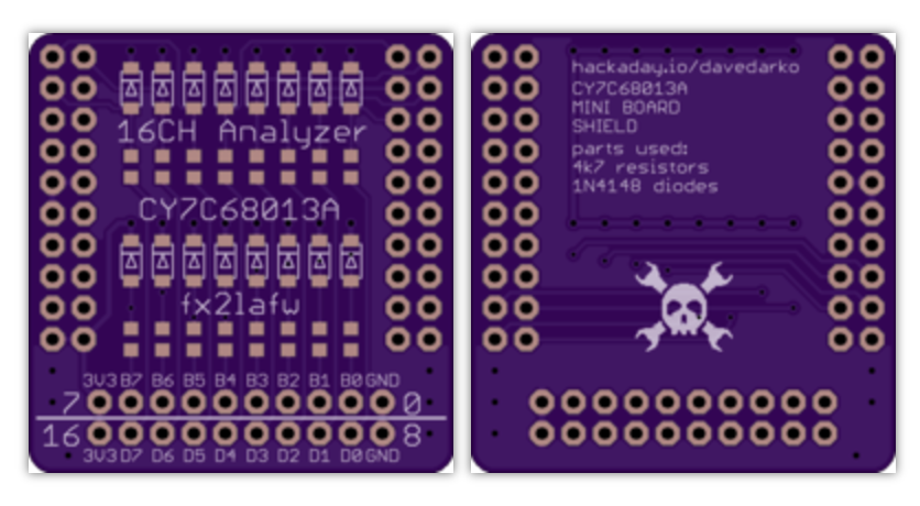
I've made a little board / shield, to go on top of the module, since the pinout is less optimal. It's based on the suggestions of the sigrok pages, some resistors and diodes for protection.

Porygon V2 - but not the evolution of Porygon | I took no pictures, so here is a horrible fritzing "schematic"
2017-03-05 15:09:16
The walking puppy Sketch for the Arduino is in the file section, as is this picture and the latest, unprinted revision of 3D files. There is still no glue and the perfect version would have to have a 2 part head section and screws on the body. Take a bigger battery though, something like >160mAh?
Game Boy Cartridge plus Programmer | Another idea
2017-03-04 12:47:20
I will not persue this :D but having a lot of game boy pockets coming in, that have a broken display... I wonder if there could be a feasible replacement like an fpga / arm controlled display that grabs the input like the fpga vga adapter does. There was a blog post once and it was also integrated into the huge ben heck game boy. Could be interesting to try for someone whos into fpgas and gameboys.
Porygon V2 - but not the evolution of Porygon | Needs another revision or two
Porygon V2 - but not the evolution of Porygon | This will be enough to work with
2017-03-03 19:46:16

blinking things | 2nd try - this time with SK6812 LEDs
2017-03-03 18:51:37
Definitely mooooaaar white :)

Porygon V2 - but not the evolution of Porygon | dual sided power rail thing
2017-03-03 16:48:43
inspired by Game Boy Pi Zero hackers and the pure need to solder man servos to ground and vcc...

blinking things | Got scammed on aliexpress? meh
2017-03-01 12:40:59
So I thought I've bought the new SK6812 with RGBNW on aliexpress.com, but instead I received some standard RGB WS2812 LEDs - not cool :( but the shield works. Now I've bought half of the LEDs for the same price on eBay, let's see how that will turn out ;) dispute on aliexpress was opened, hoping for at least some refund.


Game Boy Cartridge plus Programmer | Bivert Module
2017-03-01 00:55:05

The bivert module I bought from handheldlengend.com has some design flaws, the unused inverters aren't grounded and there is no decoupling capacitor. So for future mods I will use one of these boards that feature a dual inverter named SN74LVC2G04. It's also smaller and potentially easier to install in the Game Boy Pocket.
UPDATE: there is a smaller version for Game Boy Pockets to buy already at http://store.kitsch-bent.com/product/gb-pocket-lcd-inverter
UPDATE2: a redesign with an dual XOR chip might be interesting, to revert the bivert. Sounds like a dance move :D
Game Boy Cartridge plus Programmer | this is so pleasing!
2017-02-28 22:14:28
I've "biverted" and added a backlight to the not so cheap Game Boy Pocket I own not so long :) This means testing homebrew cartridges with style! This is the yellow backlight of www.handheldlegends.com - the hex inverter module was quite the hassle with a Game Boy pocket. I should have designed it myself, but also wanted to support the website.
