https://learn.adafruit.com/trinket-audio-player/sound-playback
http://www.technoblogy.com/show?QBB
| 2026 | 2024 | 2023 | 2022 | 2021 | 2020 | 2019 | 2018 | 2017 | 2016 | 2015 | 2014 |
|---|---|---|---|---|---|---|---|---|---|---|---|
| 2 | 2 | 11 | 15 | 23 | 13 | 30 | 72 | 152 | 102 | 134 | 62 |
https://learn.adafruit.com/trinket-audio-player/sound-playback
http://www.technoblogy.com/show?QBB
I'll be in America from mid September to mid October, afterwards I'll buy some new lab furniture :)
Ikea Billy 0.8m width on 3.4m
4 billys 54euros each
216 total
I still have to update the OSHpark Board, there are some minor label changes (if it works at all, that is :D ):
C2 is a 10nF cap
C1 is a10uF cap
So this board should have all the bells and whistles it can:

And for the money I've bought some more boards, this time black pcbs from dirtypcbs.com though - sorry to every other vendor, but please add eagle brd file support :D Anyway, I wanted to have some black K.I.T.T.s with red LEDs as well.
LCD Controller replacement
scrapped, I have #LAMEBOY - another ESP12 handheld and neon pink 3D printing filament now, I don't need this anymore and it's already gone :D

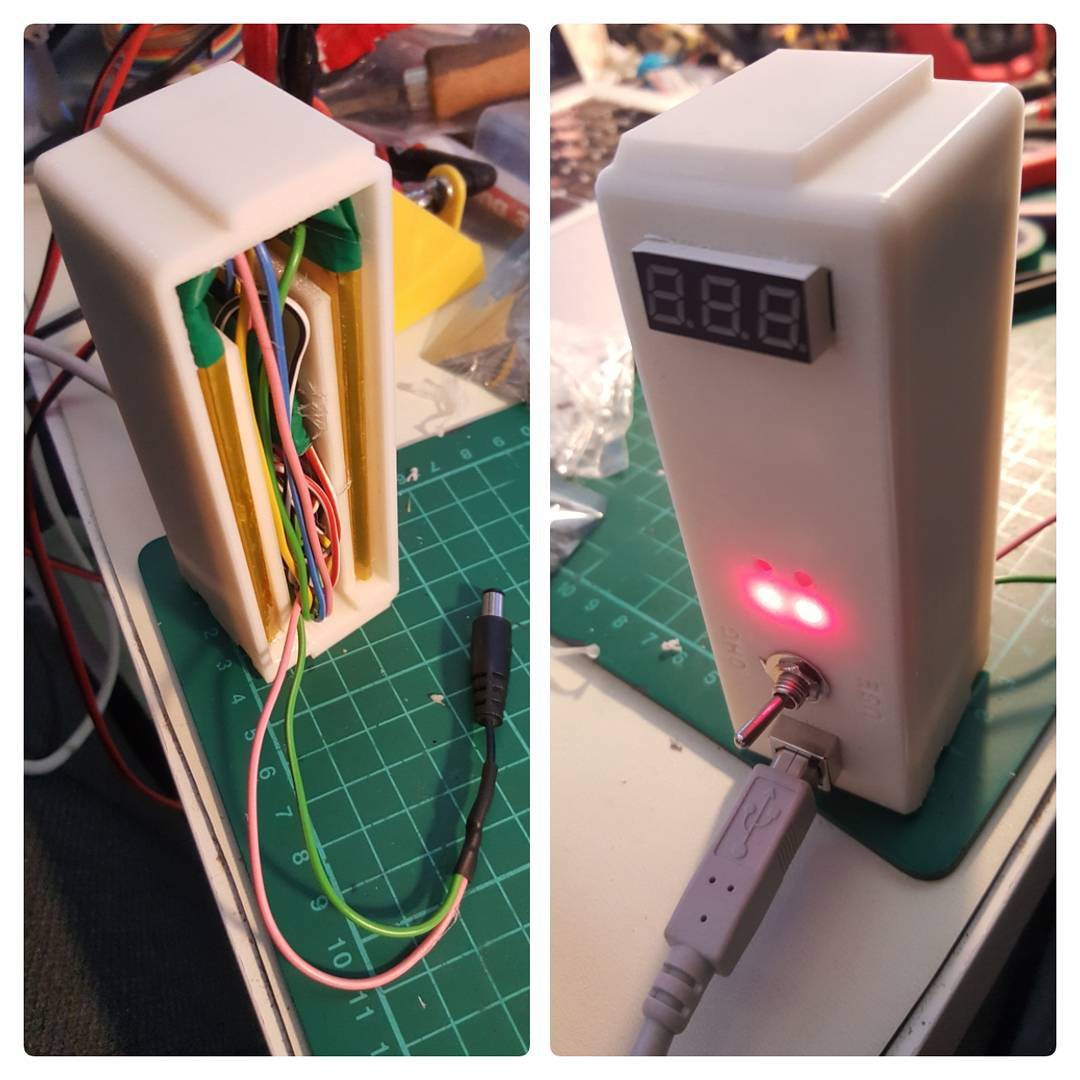
So I thought that my LiPo Chargers in form of 4056 modules are all weird, broken and not powerful enough, until I've noticed that my UNI-T UT61E multimeter isn't calibrated anymore(?)! Stupid me also calibrated other stuff like my Power Supply made from a buck down converter and a notebook PSU using that meter. I also thought my R8D8 power bank was off big time and the batteries were done, because I've continuously measured 3.8V on each cell with that multimeter... meh. Cheap multimeter now tells me I'm stupid. meh.
Anyone any tips for voltage references? Or how I can recalibrate voltage without another multimeter?
[update] I've seem to programmed all my attiny13 for #FLUX capacitor trinket with 13V instead of 12V, thanks to my multimeter... meh. but hey, they work.
http://blog.spitzenpfeil.org/wordpress/projects/youyue-858d-hotair-station-modifications/
http://www.heartoftechnology.com/project-858d-hot-air-rework-station/
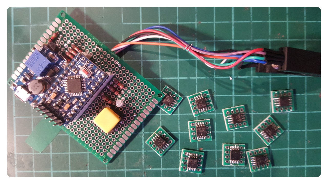
to fix almost all my tiny13a's I had to build this, but it definitely fixed all 10 boards :) for the tinies you don't need any parallel connections, so it's basically SPI + 12V on reset. I've hooked up a boost converter, added a button and "some" LEDs (bicolor), worked them in the code and now basically have a "power on and fix" stand alone fuse resetter for soic Attinies. That's not highly specialised at all. BUT IT WORKS AND THEY WORK! Now I need to clean up my desk.
http://www.engbedded.com/fusecalc/
https://arduinodiy.wordpress.com/2015/05/16/high-voltage-programmingunbricking-for-attiny/
// AVR High-voltage Serial Fuse Reprogrammer
// Adapted from code and design by Paul Willoughby 03/20/2010
// http://www.rickety.us/2010/03/arduino-avr-high-voltage-serial-programmer/
// Fuse Calc:
//   http://www.engbedded.com/fusecalc/
// slightly edited by davedarko in 2017

#define  RST     13    // Output to level shifter for !RESET from transistor
#define  SCI     12    // Target Clock Input
#define  SDO     11    // Target Data Output
#define  SII     10    // Target Instruction Input
#define  SDI      9    // Target Data Input
#define  VCC      8    // Target VCC

#define  BUTTON   3    // Target VCC
#define  LED_RED  7    // Target VCC
#define  LED_GRN  5    // Target VCC

#define  HFUSE  0x747C
#define  LFUSE  0x646C
#define  EFUSE  0x666E

// Define ATTiny series signatures
#define  ATTINY13   0x9007  // L: 0x6A, H: 0xFF             8 pin
#define  ATTINY24   0x910B  // L: 0x62, H: 0xDF, E: 0xFF   14 pin
#define  ATTINY25   0x9108  // L: 0x62, H: 0xDF, E: 0xFF    8 pin
#define  ATTINY44   0x9207  // L: 0x62, H: 0xDF, E: 0xFFF  14 pin
#define  ATTINY45   0x9206  // L: 0x62, H: 0xDF, E: 0xFF    8 pin
#define  ATTINY84   0x930C  // L: 0x62, H: 0xDF, E: 0xFFF  14 pin
#define  ATTINY85   0x930B  // L: 0x62, H: 0xDF, E: 0xFF    8 pin

void setup() {
  pinMode(BUTTON, INPUT_PULLUP);
  pinMode(LED_GRN, OUTPUT);
  pinMode(LED_RED, OUTPUT);

  pinMode(VCC, OUTPUT);
  pinMode(RST, OUTPUT);
  pinMode(SDI, OUTPUT);
  pinMode(SII, OUTPUT);
  pinMode(SCI, OUTPUT);
  pinMode(SDO, OUTPUT);     // Configured as input when in programming mode
  digitalWrite(RST, HIGH);  // Level shifter is inverting, this shuts off 12V
  Serial.begin(19200);
}

void loop() {
  digitalWrite(LED_GRN, HIGH);
  digitalWrite(LED_RED, LOW);

  if (digitalRead(BUTTON) == LOW)
  {
    digitalWrite(LED_GRN, LOW);
    digitalWrite(LED_RED, HIGH);

    pinMode(SDO, OUTPUT);     // Set SDO to output
    digitalWrite(SDI, LOW);
    digitalWrite(SII, LOW);
    digitalWrite(SDO, LOW);
    digitalWrite(RST, HIGH);  // 12v Off
    digitalWrite(VCC, HIGH);  // Vcc On
    delayMicroseconds(20);
    digitalWrite(RST, LOW);   // 12v On
    delayMicroseconds(10);
    pinMode(SDO, INPUT);      // Set SDO to input
    delayMicroseconds(300);
    unsigned int sig = readSignature();
    Serial.print("Signature is: ");
    Serial.println(sig, HEX);
    readFuses();
    if (sig == ATTINY13) {
      writeFuse(LFUSE, 0x6A);
      writeFuse(HFUSE, 0xFF);
    } else if (sig == ATTINY24 || sig == ATTINY44 || sig == ATTINY84 ||
               sig == ATTINY25 || sig == ATTINY45 || sig == ATTINY85) {
      writeFuse(LFUSE, 0x62);
      writeFuse(HFUSE, 0xDF);
      writeFuse(EFUSE, 0xFF);
    }
    readFuses();
    digitalWrite(SCI, LOW);
    digitalWrite(VCC, LOW);    // Vcc Off
    digitalWrite(RST, HIGH);   // 12v Off
    delay(1000);
  }
}

byte shiftOut (byte val1, byte val2) {
  int inBits = 0;
  //Wait until SDO goes high
  while (!digitalRead(SDO))
    ;
  unsigned int dout = (unsigned int) val1 << 2;
  unsigned int iout = (unsigned int) val2 << 2;
   for (int ii = 10; ii >= 0; ii--)  {
    digitalWrite(SDI, !!(dout & (1 << ii)));
    digitalWrite(SII, !!(iout & (1 << ii)));
    inBits <<= 1;         inBits |= digitalRead(SDO);
     digitalWrite(SCI, HIGH);
     digitalWrite(SCI, LOW);
   }
   return inBits >> 2;
}

void writeFuse (unsigned int fuse, byte val) {
  shiftOut(0x40, 0x4C);
  shiftOut( val, 0x2C);
  shiftOut(0x00, (byte) (fuse >> 8));
  shiftOut(0x00, (byte) fuse);
}

void readFuses () {
  byte val;
        shiftOut(0x04, 0x4C);  // LFuse
        shiftOut(0x00, 0x68);
  val = shiftOut(0x00, 0x6C);
  Serial.print("LFuse "); // this line may show up corrupted in some browsers it is a Serial.print("LFuse: ");
  Serial.print(val, HEX);
        shiftOut(0x04, 0x4C);  // HFuse
        shiftOut(0x00, 0x7A);
  val = shiftOut(0x00, 0x7E);
  Serial.print(", HFuse: ");
  Serial.print(val, HEX);
        shiftOut(0x04, 0x4C);  // EFuse
        shiftOut(0x00, 0x6A);
  val = shiftOut(0x00, 0x6E);
  Serial.print(", EFuse: ");
  Serial.println(val, HEX);
}

unsigned int readSignature () {
  unsigned int sig = 0;
  byte val;
  for (int ii = 1; ii < 3; ii++) {
          shiftOut(0x08, 0x4C);
          shiftOut(  ii, 0x0C);
          shiftOut(0x00, 0x68);
    val = shiftOut(0x00, 0x6C);
    sig = (sig << 8) + val;
  }
  return sig;
}Thanks to @al1 I'm now aware that I've mixed up the GND and VCC symbols from the schematics of @Elliot Williams :D So now it's corrected and everything looks even cleaner! Definitely will sleep on ordering this one (hopefully al1 will have another look, just to be sure) :D I'm not looking forward to the boards arrival - straight to the totem of failure, I guess.

Okay, here we go:
Left OSHPark board: attiny13a SSU - working
Right OSHPark board: attiny45 - working
all 10 green boards: attiny13a SU - not working
Red board: attiny13a SSU - not working (but same badge as left OP board - weird)
USB cable tester: attiny13a SSU - working
small OSHPark board: attiny13a SSU - no idea
out of 15 attiny13a boards I know that two are working :( meh. At first I thought The smaller tinies are definitely fake, but the datasheet says they're a possibility.

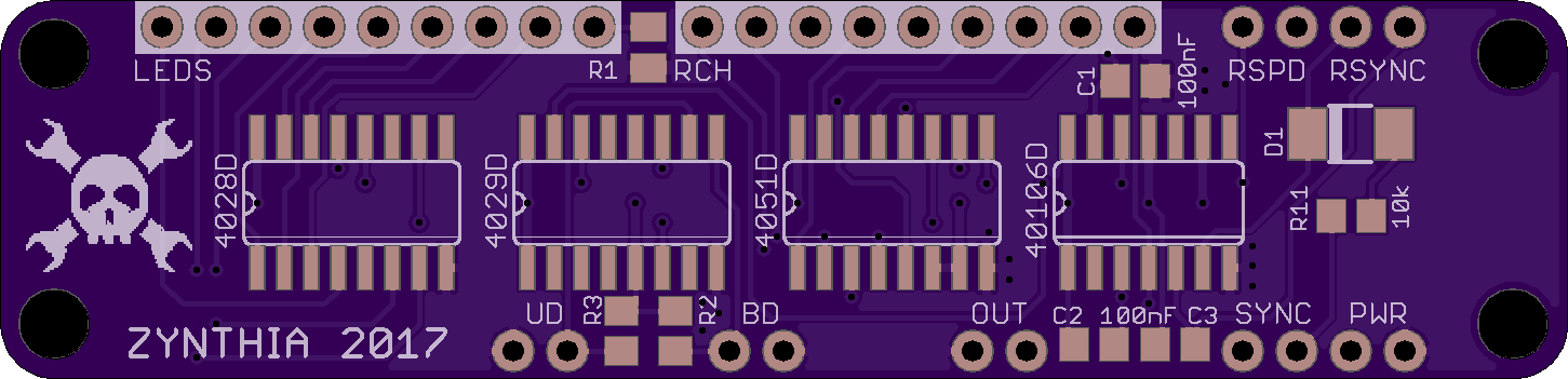
I came around to design an SMD version of the perfboard version :)
On board is:
- 8ch LED port
- 8ch potentiometer port
- counting up/down switch
- octade (binary) / decade switch
- synced pitch switch and potentiometer
- speed potentiometer

I was looking for color coding standards and connectors for I2C, hopefully something cheap. I found Grove I2C connectors instead. Now I've ordered some connectors, cables and hubs to connect sensors and mcus - which hopefully makes developing and later adding new sensors easier.
A little enclosure for the VL53L0X Time of Flight laser sensor module - one of the elongated, purple-pinkish once.

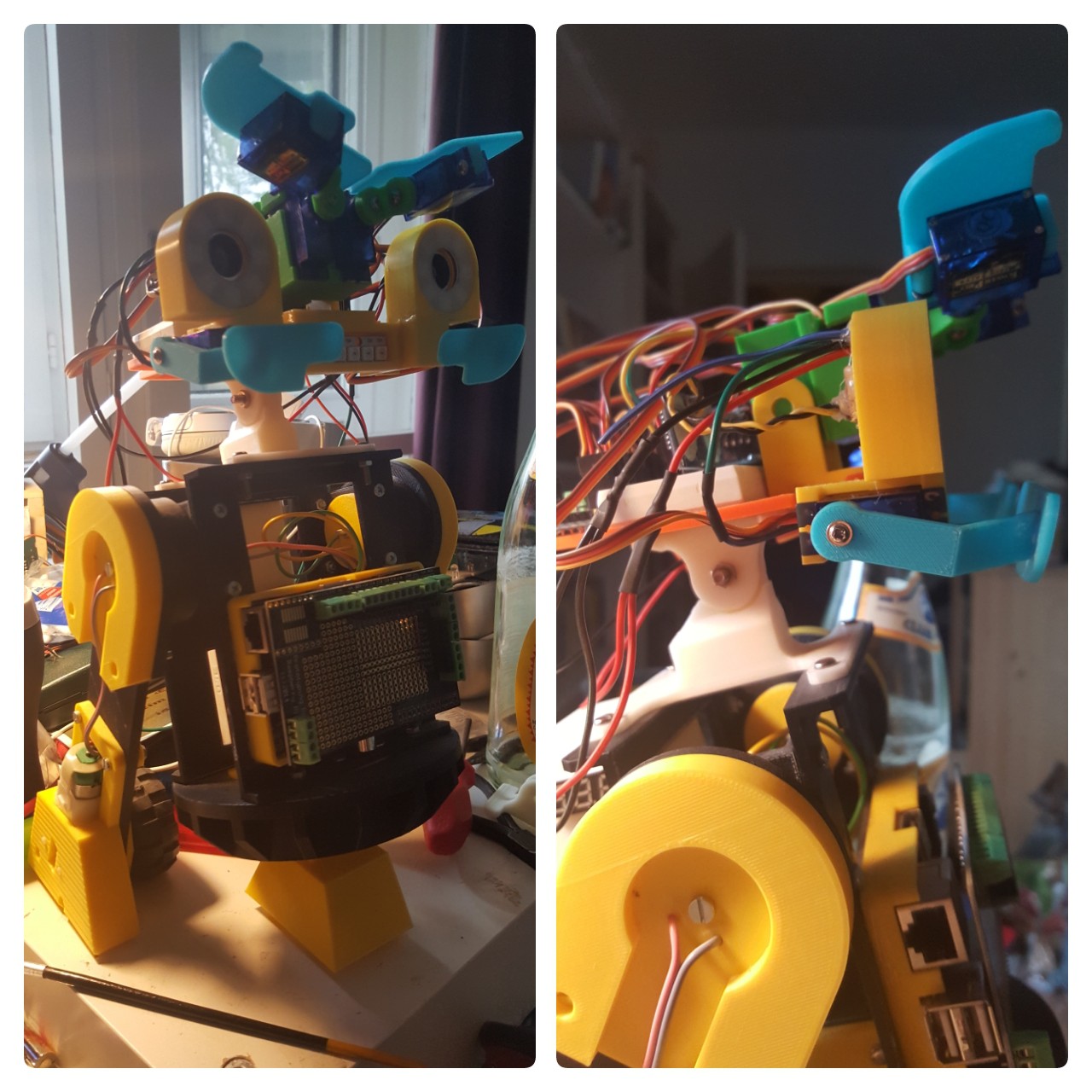
I never came around to actually mount Johnnys head to my #R8-D8 - a distant relative of R2-D2 - it's possible to even motorize it later, but for now it's just fixed and transportation is way easier now! Currently in revision is a 3D printed case for the vl53l0x, to protect the module that replaces the interactive ultrasonic module. What other robot could I throw in there to mash up?
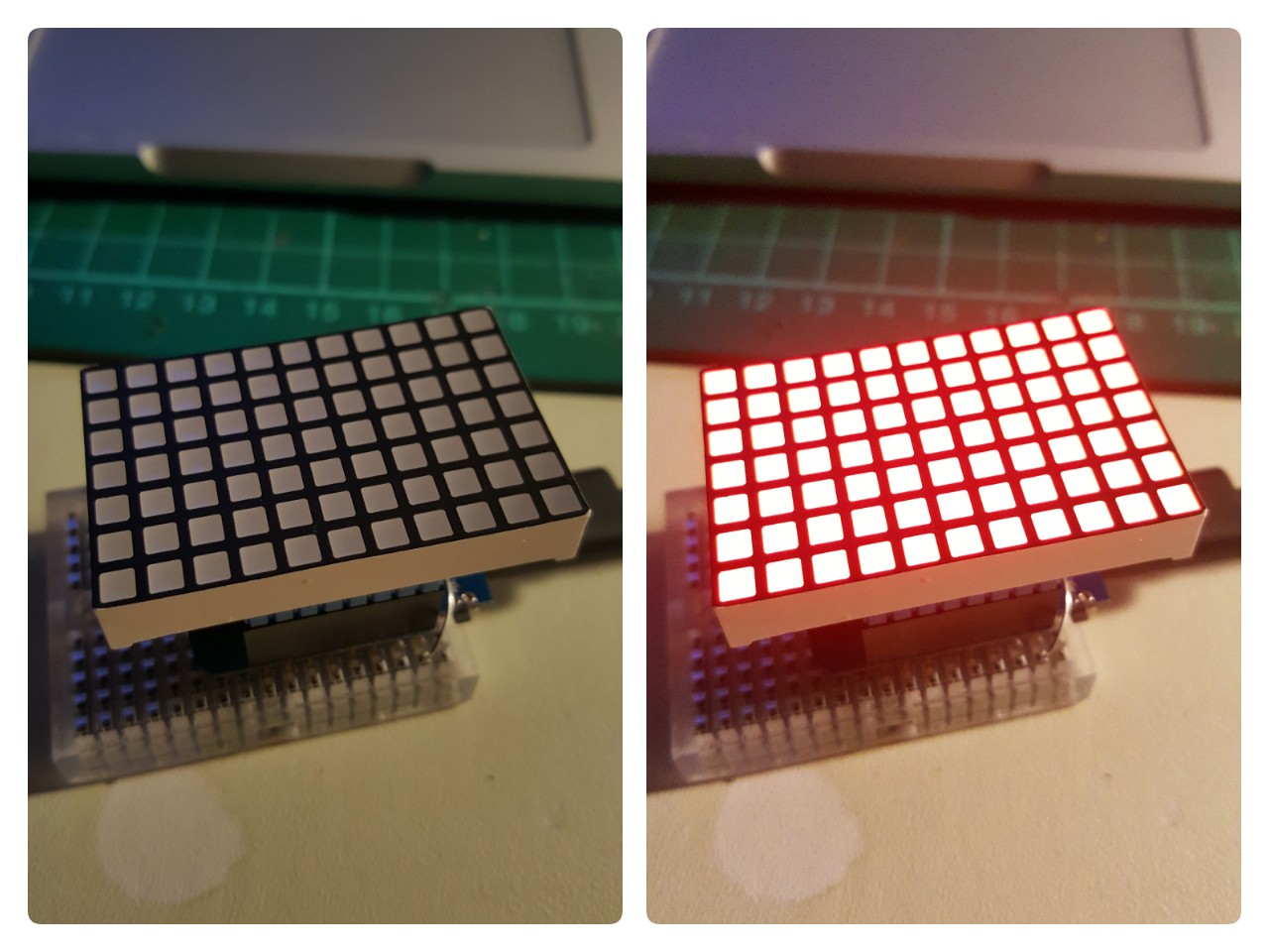
Trying to make [this] work with the Arduino IDE on a Wemos D1 Mini. The additional capacitor got loose, so that there were fluctuations in one row. One row seems to be dead now, after I tried to resolder the QFN chip with my soldering iron. Instead of fiddeling around with that anymore, I finally got around to fix my hot air station. One of the 230V cables was crimped wrong, there was still some isolation where there should have been the blank cable, I wonder why it ever worked at first. There's a DIP Atmega8L inside - funky.
#include <Wire.h>
byte address = 0x50;
void setup() {
  Wire.begin();
  activate();
}
void loop() {
  ledPWM(255);
  delay(1000);
  ledPWM(0);
  delay(1000);
}
void ledPWM(byte b)
{
  // Wire.write(byte(0x00));
  for (byte i=0; i<98; i++)
  {
    writeEnable(byte(0x01));
    Wire.beginTransmission(address);
    Wire.write(i*2);
    Wire.write(b);
    Wire.endTransmission();
  }
}
void turnOnLeds()
{
  writeEnable(byte(0x00));
  Wire.beginTransmission(address);
  Wire.write(byte(0x00));
  for (byte i=0; i<12; i++)
  {
    Wire.write(byte(0x55));
    Wire.write(byte(0x15));
  }
  Wire.endTransmission();
}
void releaseRegister()
{
  Wire.beginTransmission(address);
  Wire.write(byte(0xfe));  // send command
  Wire.write(byte(0xc5));  // send page zero
  Wire.endTransmission();
}
void writeEnable(byte page)
{
  releaseRegister();
  Wire.beginTransmission(address);
  Wire.write(byte(0xfd));  // send command
  Wire.write(page);  // send page zero
  Wire.endTransmission();
}
void activate()
{
  writeEnable(byte(0x03));
  Wire.beginTransmission(address);
  Wire.write(byte(0x00));  // Configuration Register
  Wire.write(byte(0x01));  // Set SSD = 1
  Wire.endTransmission();
  writeEnable(byte(0x03));
  Wire.beginTransmission(address);
  Wire.write(byte(0x01));  // Global Current Control
  Wire.write(byte(0x30));  // set to 127
  Wire.endTransmission();
  turnOnLeds();
}
(OTA doesn't work with current chip)
#include <ESP8266WiFi.h>
#include <ESP8266mDNS.h>
#include <WiFiUdp.h>
#include <ArduinoOTA.h>
#include <Wire.h>
#include <LiquidCrystal_I2C.h>
LiquidCrystal_I2C lcd[8] = {
  LiquidCrystal_I2C(0x27, 16, 2),
  LiquidCrystal_I2C(0x26, 16, 2),
  LiquidCrystal_I2C(0x25, 16, 2),
  LiquidCrystal_I2C(0x24, 16, 2),
  LiquidCrystal_I2C(0x23, 16, 2),
  LiquidCrystal_I2C(0x22, 16, 2),
  LiquidCrystal_I2C(0x21, 16, 2),
  LiquidCrystal_I2C(0x20, 16, 2)
};
int LED = 0;
int sda = 4;
int scl = 5;
int current_lcd = 0;
int current_lcd_line = 0;
const char* ssid = "XXX";
const char* password = "XXX";
const char* clientID = "octoLCD";
const char* host = "your.hostname.com";
void setup() {
  Serial.begin(115200);
  Serial.println("Booting");
  Wire.begin(sda, scl);
  for (int i=0; i<8; i++)
  {
    lcd[i].init();
  }
  for (int i=0; i<8; i++)
  {
    lcd[i].backlight();
  }
  setup_wifi();
  // Hostname defaults to esp8266-[ChipID]
  ArduinoOTA.setHostname(clientID);
  // No authentication by default
  ArduinoOTA.setPassword((const char *)"PASSWORD");
  ArduinoOTA.onStart([]() {
    Serial.println("Start");
  });
  ArduinoOTA.onEnd([]() {
    Serial.println("\nEnd");
  });
  ArduinoOTA.onProgress([](unsigned int progress, unsigned int total) {
    Serial.printf("Progress: %u%%\r", (progress / (total / 100)));
  });
  ArduinoOTA.onError([](ota_error_t error) {
    Serial.printf("Error[%u]: ", error);
    if (error == OTA_AUTH_ERROR) Serial.println("Auth Failed");
    else if (error == OTA_BEGIN_ERROR) Serial.println("Begin Failed");
    else if (error == OTA_CONNECT_ERROR) Serial.println("Connect Failed");
    else if (error == OTA_RECEIVE_ERROR) Serial.println("Receive Failed");
    else if (error == OTA_END_ERROR) Serial.println("End Failed");
  });
  ArduinoOTA.begin();
}
void setup_wifi() {
  delay(10);
  // We start by connecting to a WiFi network
  Serial.println();
  Serial.print("Connecting to ");
  Serial.println(ssid);
  WiFi.mode(WIFI_STA);
  WiFi.begin(ssid, password);
  while (WiFi.status() != WL_CONNECTED) {
    delay(500);
    Serial.print(".");
  }
  Serial.println("");
  Serial.println("WiFi connected");
  Serial.println("IP address: ");
  Serial.println(WiFi.localIP());
}
void loop()
{
  ArduinoOTA.handle();
  WiFiClient client;
  const int httpPort = 80;
  if (!client.connect(host, httpPort)) {
    Serial.println("connection failed");
    return;
  }
  delay(10);
  String url = "/81602/index.php";
  client.print(String("GET ") + url + " HTTP/1.1\r\n" +
               "Host: " + host + "\r\n" +
               "Connection: close\r\n\r\n");
  delay(10);
  boolean ignore = true;
  reset_lcds();
  while (client.connected())
  {
    char a,b,c,d;
    if (!ignore)
    {
      String line = client.readStringUntil('\n');
      // char f = (char) client.read();
      Serial.println(line);
      draw(line);
      // lcd[0].print(a);
      // lcd[0].setCursor(0,0);
    }
    else
    {
      a = client.read();
      if (a == 13)
      {
        b = client.read();
        if (b == 10)
        {
          c = client.read();
          if (c == 13)
          {
            d = client.read();
            if (d == 10)
            {
              ignore = false;
            }
          }
        }
      }
    }
  }
  delay(15000);
}
void draw (String line)
{
  lcd[current_lcd].print(line);
  if (current_lcd_line==1)
  {
    current_lcd_line = 0;
    if (current_lcd<7) current_lcd++;
  }
  else
  {
    lcd[current_lcd].setCursor(0,1);
    current_lcd_line = 1;
  }
}
void reset_lcds()
{
  current_lcd = 0;
  current_lcd_line = 0;
  for (int i=0; i<8; i++)
  {
    lcd[i].clear();
  }
}
So the data is served by a webpage, but it's still a mockup. But yay!
noooo.
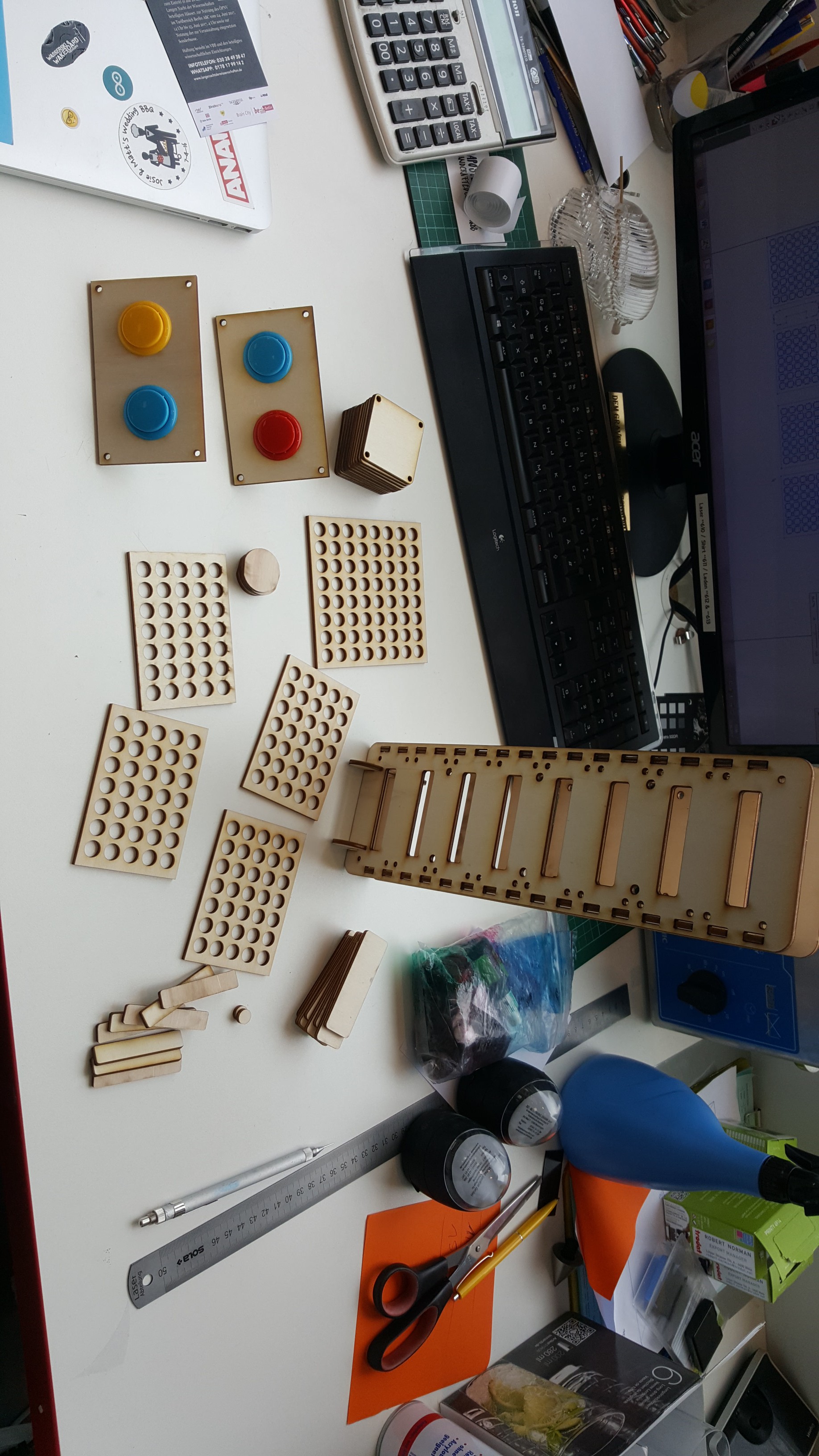
[2018-10-03] Turns out my schematics were bad and basically shortened one battery when in "use" setting. The after math: one LiPo is trash, as well as the charger. Today I've rebuild the charger with normal TP4056 modules, no protection and strictly followed the tutorial.