done! :)
| 2026 | 2024 | 2023 | 2022 | 2021 | 2020 | 2019 | 2018 | 2017 | 2016 | 2015 | 2014 |
|---|---|---|---|---|---|---|---|---|---|---|---|
| 2 | 2 | 11 | 15 | 23 | 13 | 30 | 72 | 152 | 102 | 134 | 62 |
done! :)
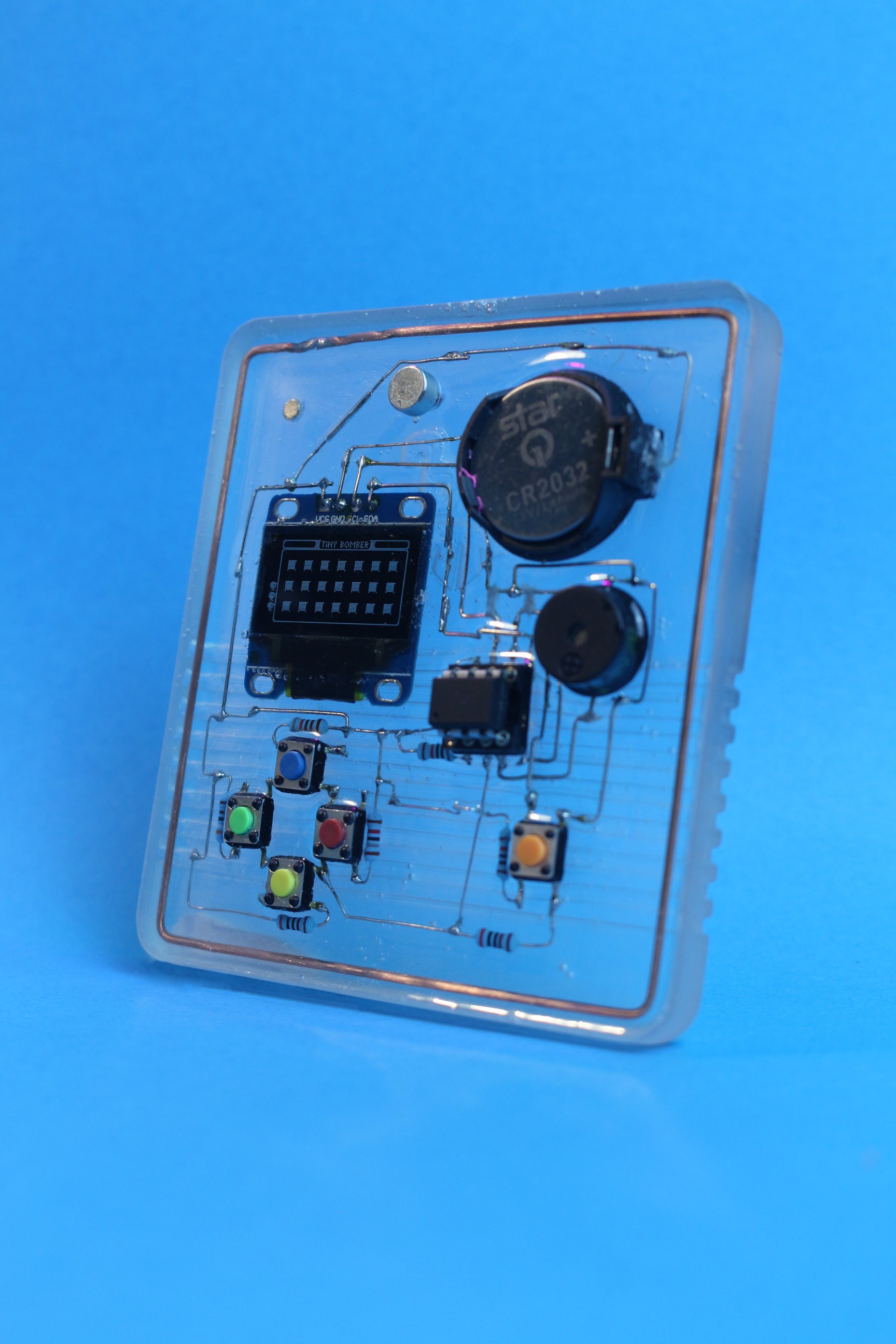
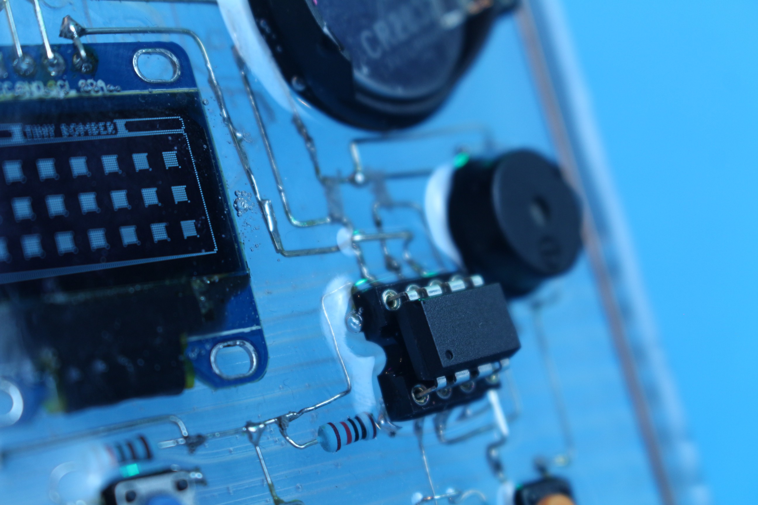
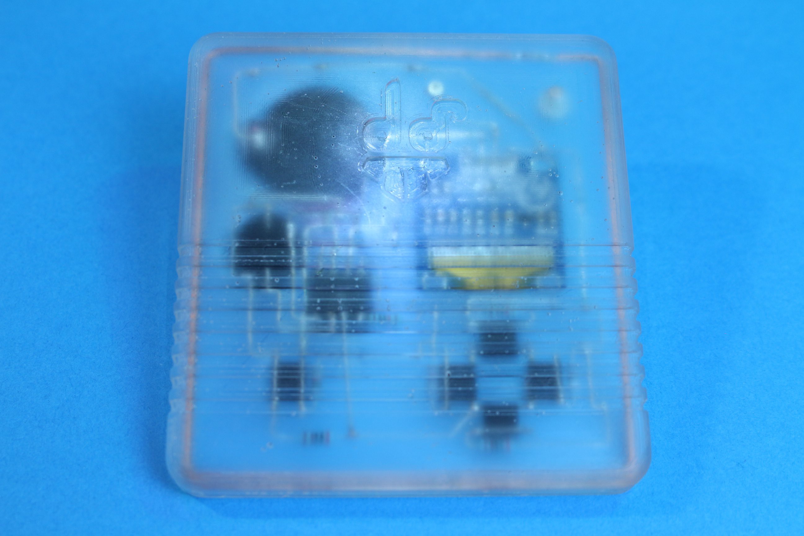
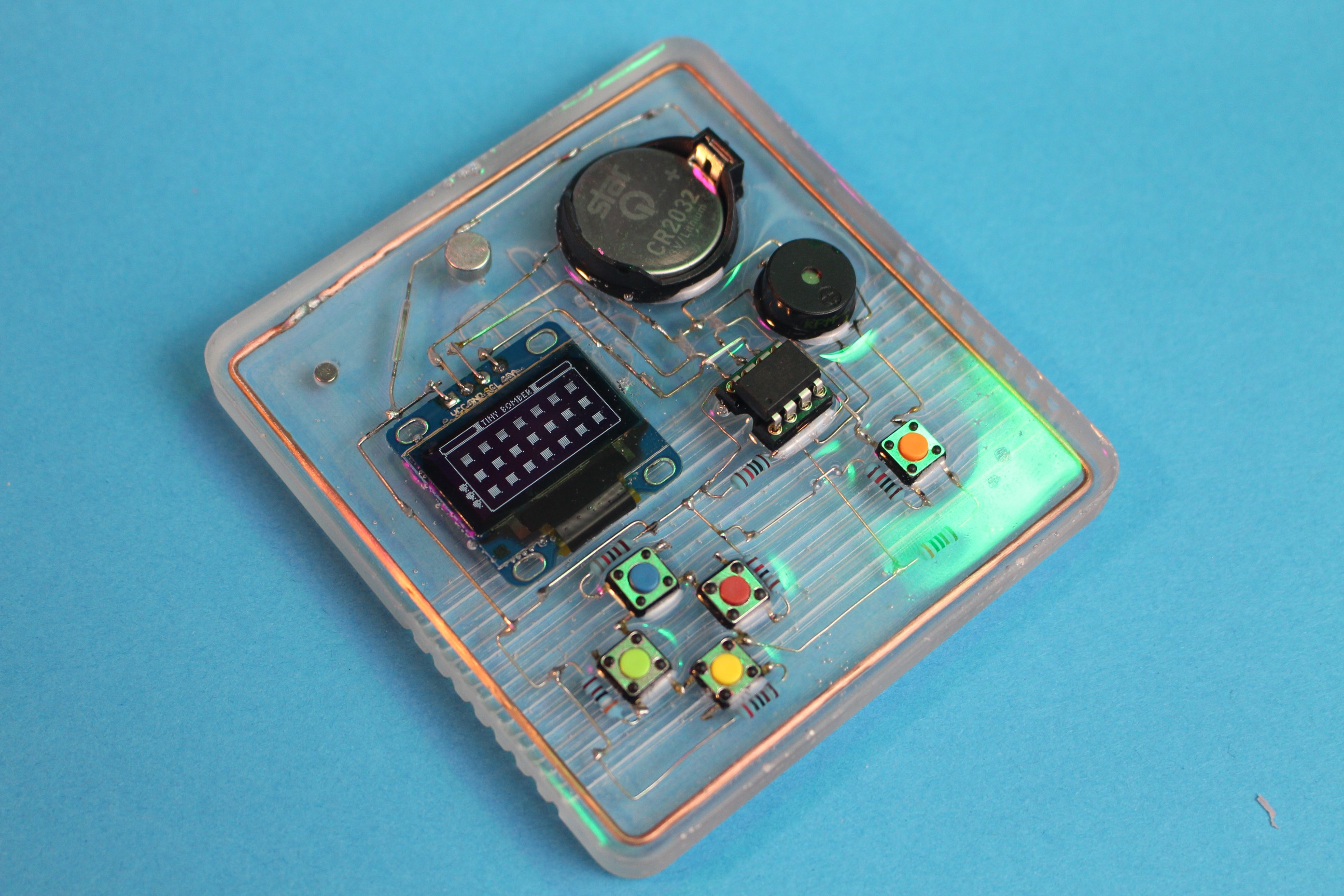
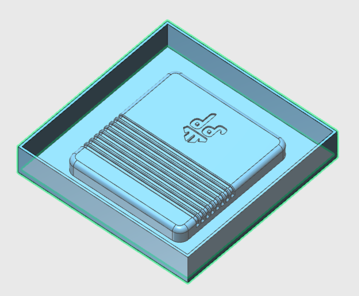
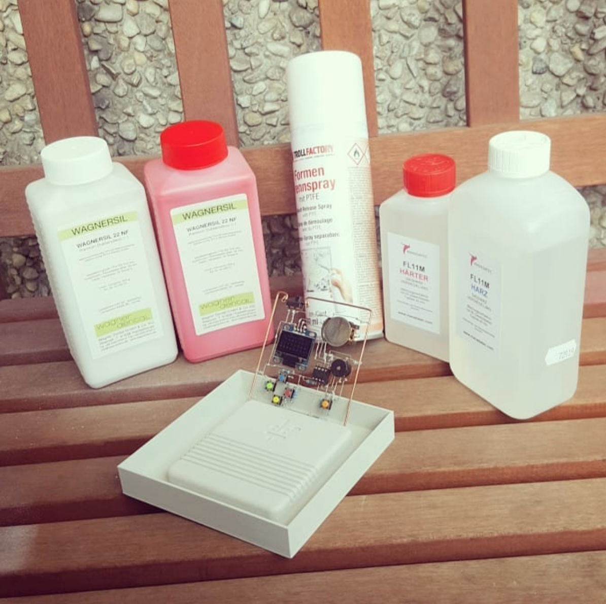
I bought a bunch of things as a result of the feedback in the video comments and what people said before that already - basically a whole set for casting stuff in resin. Then I designed a case mould in 123D Design where I would cast the negative silicone mould in. The silicone came out wonderfully, but when I tried to pre-seal the switch and IC socket, the resin got into the parts, meaning I have to resolder them. It also seems as if the ratio wasn't mixed 100% right, as the resin is still very liquid, although it has been poured 3-4 hours ago. If it is not hard tomorrow morning, then I will mix up a new batch and remove the first layer of resin to start over.
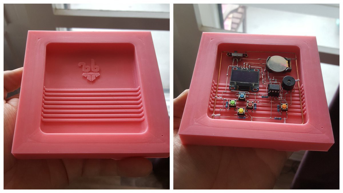
So I made a revision of this project for my first episode for element14 :)
Some nice beautiful purple boards arrived at home today, but I'm trapped with three dudes in a trailer house in Luxembourg for the next 12 days :D

I'm scared of that rats nest of wires on a breadboard that is hidden in a box. Thanks to some experience I gained with using IO0 and IO2 as a regular pin, I know that it's okay to use them as the missing two address line pins. I might steal one of them back to be able to reset the game boy, as I don't think using one of the serial pins is a good idea, especially if you want to have a serial debug terminal ;)
With less address pins the programs written / compiled for should adjust memory bank switching for smaller banks. I think that's doable.
Not sure if I said this here, but I was able to run the I2S parallel code on the ESP32 and that gave me hope. After a lot of unexpected twitter feedback about groundplanes and copper tunges, I made some changes and this is what I came up with. Cleanly routed, doesn't fit any reproduction cartridges, but form follows function, right? There's even a 1M ohm connecting the usb connector shield to Ground (not even sure if this is 100% necessary, but better safe then sorry, right?
Power consumption of the ESP vs. 4 AA batteries inside a DMG or even worse - 2 AAA batteries inside a GB Pocket is still an issue with this board. The plan is to have one AAA LiPo added to a later revision of the board. To get an idea how this could look like, check out the Pokemon Pinball cartridge, or any Game Boy rumble cartridge for that matter. This design is supposed to be powered over USB, since it's a dev / debug board.
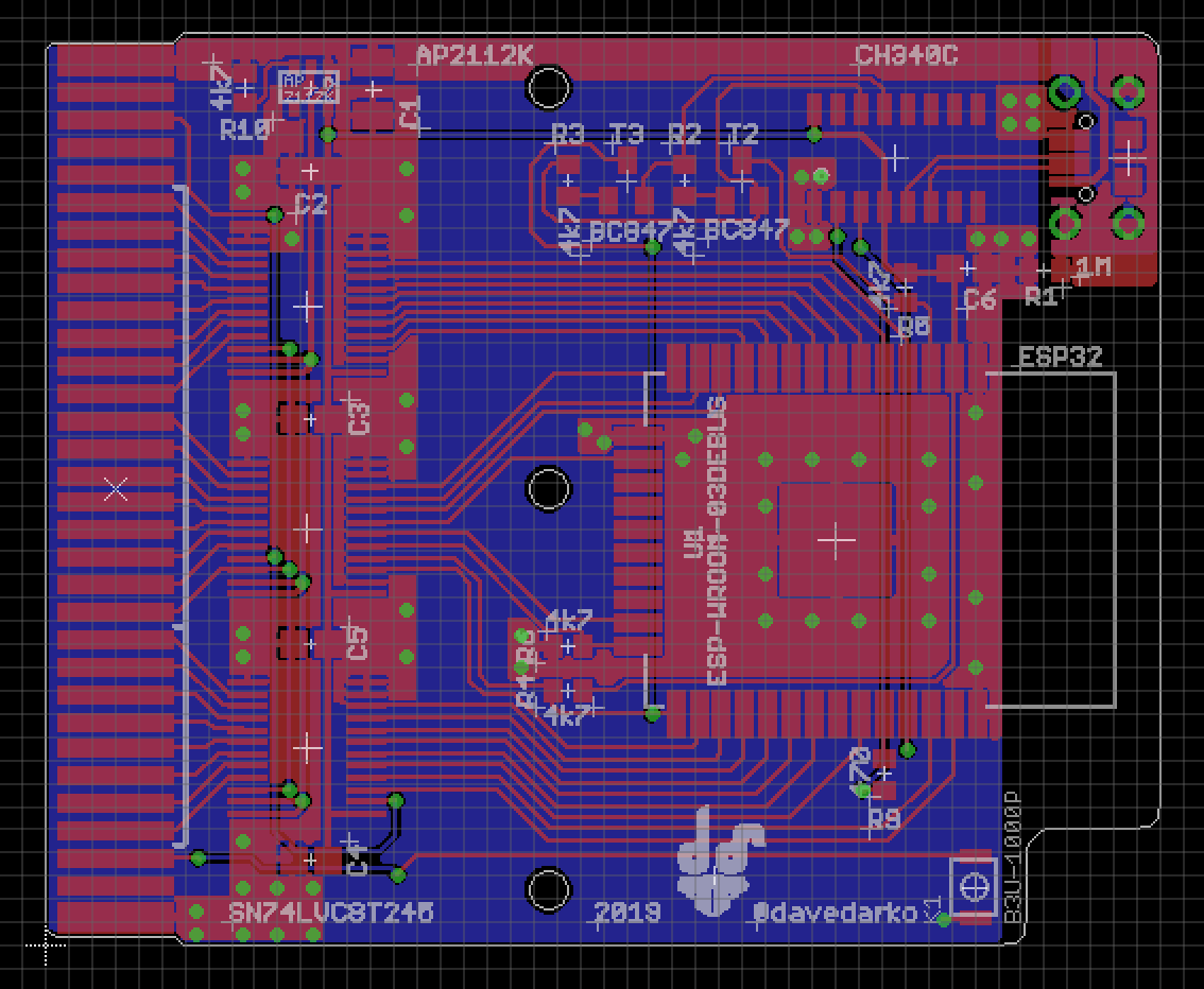
After I read 2.7V on the VCC pins it finally made click - the VCC pins weren't connected to the 3.3V pin, but got voltage through diodes on the enable and SPI pins. This made me so happy, that I bought some new boards and parts and I will make this a tindie product at one point.

@WooDWorkeR asked me to join the Drehkommando meetup at c-base and since I also had to bring him some goodies from the Chaos Communication Congress, I couldn't say no :D https://twitter.com/woodworker/status/1084192948718370816 we were able to add zynthia 2.0 to the pile of wires and noise gadgets and it didn't sound too bad. Especially when played loud ;)
But I noticed some issues that I wanted to work on later. I had no control over volume at all, something I was able to fix with a variable resistor used as a voltage divider on the output. I also had a lot of high pitched noise on the output, something that I wanted to tackle with a High Pass filter. Yes, you've read that right - I was stupid until I noticed I need a Low _PASS_ filter instead :D
I then combined it with a simple dc-offset filter - there's also a High Pass filter in the schematics taken from stackexchange.

https://electronics.stackexchange.com/questions/319857/anti-aliasing-filter-dc-offset
Followed by a fixed Low Pass filter and previously mentioned volume knob. You can see spot the two signals here, yellow is coming directly from the 40106, blue is after the filter, but before the volume potentiometer.
https://www.instagram.com/p/BslYsZqnE6b/
Some slight changes to the capacitor values allow the sequencer to run a bit slower. The synced pitch mode now has a wider range of frequencies. The tone range of the knobs is now deeper.
With the pink board I also fixed the direction of the potentiometers, when you now turn them clockwise, the tones go up.
At one point I had a thought that I could vary the time between asking the charlieplexed buttons and add a piezo buzzer to one pin to get some noises out of the little handheld. But then you would have to have sound all the time, because you want to scan the buttons as well.
It would make much more sense to have the buttons connected via a bunch of resistors to the ADC, so you get free pins and a way to add a buzzer. The project I named in an earlier log is a way better basis to do so.
It was fun to solder up the prototype and build a charlieplexed "keyboard" for the first time, but programming a game for it wasn't really on the time table sadly. I enjoyed the positive feedback from everyone on social media though and might think of something at a later point. Thanks for having this contest, hackaday people!
Hehe... just noticed the countdown said "since" and not "until". Anyways, nice to add some thoughts afterwards then!
I admit it was a bit trial and error development, but it worked out in the end.
#define pin_1 1
#define pin_2 4
#define pin_3 3

#define B_UP 0
#define B_DN 1
#define B_LF 2
#define B_RT 3
#define B_A 4
#define B_B 5

boolean pinChanged = false;
uint8_t pinstate = 0;
uint8_t pins[3] = { pin_1, pin_2, pin_3 };
uint8_t switches[6][2] =
{
  { pin_2, pin_1 },
  { pin_1, pin_3 },
  { pin_3, pin_1 },
  { pin_1, pin_2 },
  { pin_3, pin_2 },
  { pin_2, pin_3 }
};


void setup()
{
}

void loop()
{
  if (pinChanged)
  {
    pinChanged = false;
    if (pinstate & (1 << B_UP))
    {
    }

    if (pinstate & (1 << B_DN))
    {
    }

    if (pinstate & (1 << B_LF))
    {
    }

    if (pinstate & (1 << B_RT))
    {
    }

    if (pinstate & (1 << B_A))
    {
    }

    if (pinstate & (1 << B_B))
    {
    }
  }

  for (uint8_t i = 0; i < 6; i++)
  {
    deactivate_all();

    // set pin states for button
    pinMode(switches[i][0], INPUT_PULLUP);
    pinMode(switches[i][1], OUTPUT);
    digitalWrite(switches[i][1], LOW);


    if (pinstate & (1 << i))
    {
      if (digitalRead(switches[i][0]) == HIGH)
      {
        pinstate &= ~(1 << i);
        pinChanged = true;
      }
    }
    else
    {
      if (digitalRead(switches[i][0]) == LOW)
      {
        pinstate |= (1 << i);
        pinChanged = true;
      }
    }
  }
}

void deactivate_all()
{
  for (uint8_t i = 0; i < 3; i++)
  {
    pinMode(pins[i], OUTPUT);
    digitalWrite(pins[i], HIGH);
  }
}