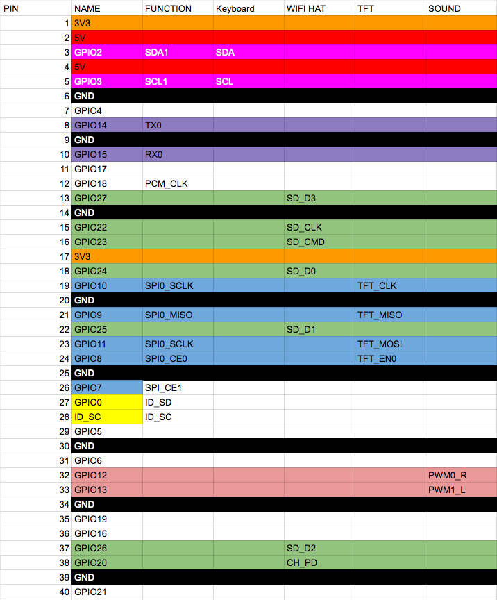
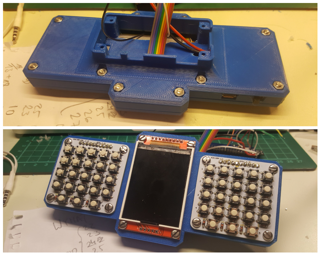
Portable Raspberry PI Zero | eyes for dem pis!
2016-11-18 09:52:52
Yay, I won something! When I saw the blog post about the Enlightened Raspberry Pi Contest I must have over looked that I won something, because I was surprised when Adam Fabio wrote me to get my address to send me a sweet camera module! Not sure if it will end up in this project or the cluster thing, but I will find a good project for it! With all those PIs I have it shouldn't be a problem.
https://hackaday.io/contest/15532/log/49182-and-the-winners-are
Game Boy Cartridge plus Programmer | Tutorial, Guidelines and Informations
Game Boy Cartridge plus Programmer | programming Game Boy games on a Mac in 2016
2016-11-17 01:21:40
First - get homebrew if you haven't.
http://brew.sh/
/usr/bin/ruby -e "$(curl -fsSL https://raw.githubusercontent.com/Homebrew/install/master/install)"

brew install wget
Then follow this for installing gbdk, or do what's in the box.
https://github.com/dunn/homebrew-formulae
brew tap mistydemeo/formulae
brew install
Then start a new.c file with your text editor of choice
nano new.c
and copy this example I borrowed from the credited site
#include <gb/gb.h>
#include <stdio.h>
void main()
{
printf("Welcome to GAMEBOY\nProgramming");
printf("\nPress Start");
waitpad(J_START);
printf("\nIsn't it easy!");
}
Run the compiler
lcc -o new.gb new.c
Lastly, get mGBA to emulate your "game" - example
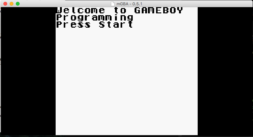
and after you hit [ENTER]
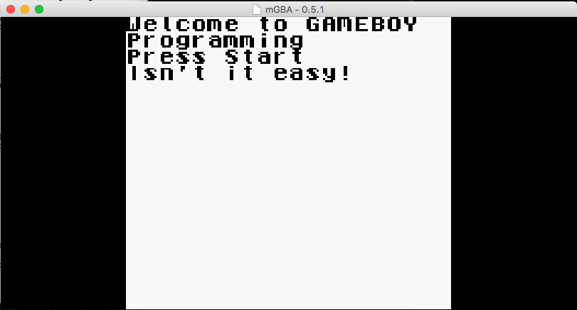
Game Boy Cartridge plus Programmer | it feels like midnight, so no order!
2016-11-15 20:00:35
Almost every pin is in use or broken out! I've ran all checks that eagle offers me, but I refuse to order because of the time!

There'a a via on the power line on the right o.O - fixed
So beautiful! - Sometimes I only upload them to see what they would look like :3


This is the LCD board that I also have to check again and order soon, not just this evening. It makes sense to have this separate, since the game boy classic also had a separate lcd board - so that's what I do, staying original :D I should make one pin header side 5V and one 3.3V and add some level converting stuff, before I order.

Game Boy Cartridge plus Programmer | It's over 9000
2016-11-14 23:30:54
Too. Much. Overkill. what started as a basic teensy++ 2.0 based cartridge reader/writer is now a full blown project with a nokia 5110 LCD display with rgb backlight, 3D printed, vintage looking case, pcb for an at90usb1286. At least in my head. Please. Somebody stop me.

I slept a night (read: 3hours) over it, I'm going to cut off the display part and will make it a separate board with mounting holes. Furthermore I will find another crystal and button and rearrange everything.

added lights to my "youtube studio"
2016-11-12 15:20:45
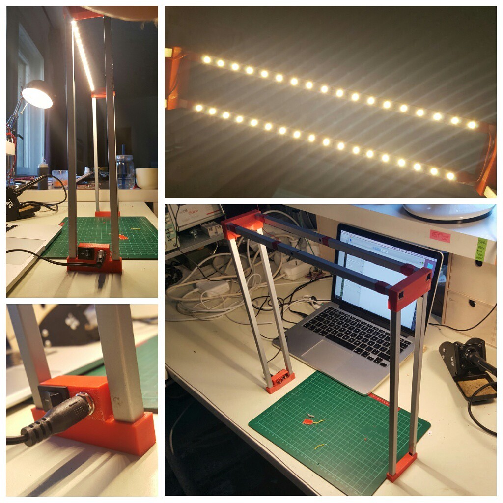
I went through the trouble of adding lights for my over head camera rig :) a little 3D print for the plug and switch was chemically welded with acetone to the existing foot. The metal beams are from a recycled IKEA lamp, to keep it hipster, the LED strip is a off of eBay for one Euro.
Portable Raspberry PI Zero | more wiring adventures
Portable Raspberry PI Zero | Odyssey continues
2016-11-09 21:55:22
Python script is about the same where I was before. Python is weird when you're coming from JS and PHP, let me tell you.
AND the uinput part works!! woot! Thanks to adafruit, mainly. And my copy and paste skills.
I still need to map the keys and find the driver for the display (MacGyver was drawn by an adafruit python library).
import subprocess
import sys
import time
import Adafruit_GPIO as GPIO
import Adafruit_GPIO.I2C as I2C
import Adafruit_GPIO.PCF8574 as PCF
import uinput
row = 1
rowI = 1
col = 1024
addressH = 0x20
addressL = 0x21
gpioH = PCF.PCF8574(addressH, busnum=1)
gpioL = PCF.PCF8574(addressL, busnum=1)
KEY_MAPPING = {
0: uinput.KEY_UP,
1: uinput.KEY_DOWN,
2: uinput.KEY_LEFT,
3: uinput.KEY_RIGHT,
4: uinput.KEY_B,
5: uinput.KEY_A,
6: uinput.KEY_ENTER,
7: uinput.KEY_SPACE,
}
subprocess.check_call(['modprobe', 'uinput'])
device = uinput.Device(KEY_MAPPING.values())
def shiftRange (start, end):
while start > end:
yield start
start = start>>1
while True:
rowS = 0x03FF ^ row
rowL = (rowS<<5) & 0x00FF
rowH = (rowS>>3) & 0x00FF
addL = rowL | 0x1F
addH = rowH
gpioH.iodir = addH
gpioL.iodir = addL
gpioH._write_pins()
gpioL._write_pins()
keys = gpioL._read_pins()
keys = keys & 0x1F;
keysI = 1
for k in shiftRange(16,0):
if k & keys == 0:
device.emit_click(KEY_MAPPING[rowI-1])
time.sleep(0.5)
keysI += 1
rowI += 1
row = row << 1
if row == col:
row = 1
rowI = 1
Game Boy Cartridge plus Programmer | inspirational links
Portable Raspberry PI Zero | Keyboard adventures - Episode 2
2016-11-06 01:53:28
That's my current state for the actual keyboard. I will probably drop this and move over to python, since I just don't get the uinput stuff in C and the linux input system. Hey future Dave, research before developing, you know this stuff!
https://learn.adafruit.com/mpr121-capacitive-touch-sensor-on-raspberry-pi-and-beaglebone-black/software
https://github.com/adafruit/Adafruit_Python_MPR121
#include <wiringPi.h>
#include <wiringPiI2C.h>
#include <stdio.h>
int fdH;
int fdL;
int fd;
int rpl;
int ret;
int row = 1;
int rowI = 1;
int col = 1024;
int i = 0;
int j = 0;
int k = 0;
void printByte(int a)
{
printf("\n0x");
for (j=0x8000; j>0; j=j>>1)
{
if ((a&j) > 0) printf("1");
else printf("0");
}
}
int main (void)
{
wiringPiSetup ();
fdH = wiringPiI2CSetup(0x20);
fdL = wiringPiI2CSetup(0x21);
for (;;)
{
int rowS = 0x03FF ^ row;
int rowL = (rowS<<5) & 0x00FF;
int rowH = (rowS>>3) & 0x00FF;
int addL = rowL | 0x1F;
int addH = rowH;
wiringPiI2CWrite(fdH, addH);
wiringPiI2CWrite(fdL, addL);
int keys = wiringPiI2CRead(fdL);
keys = keys & 0x1F;
int keyI = 1;
for (k=0x10; k>0; k=k>>1)
{
if (!(k & keys))
{
delay(50);
printf("%i\t%i\n", keyI, rowI);
}
keyI++;
}
rowI++;
row = row << 1;
if (row == col)
{
row = 1;
rowI = 1;
}
}
return 0 ;
}world clock thing | So much for not soldering...
2016-11-05 18:05:12
damn, I might have killed one LCD in the process, but it looks nice, especially with the red power lights on the backside. I've hooked up one of my #Ignore this ESP8266 board s via I2C and used an LCD I2C library for arduinos. Almost too easy.
Portable Raspberry PI Zero | I2C wiringPI for the PCF8574
2016-11-01 23:29:46
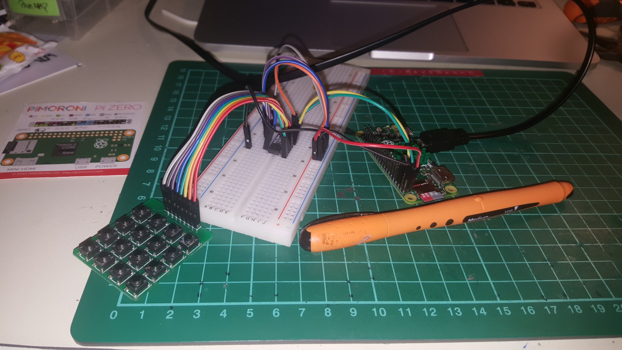
It took me a while to get this far and I'm even further away from being done. I couldn't find a good example how to use the I2C library for it. http://wiringpi.com/reference/i2c-library/
As I understand now, the function wiringPiI2CSetup gives you a file handle (everything in linux is a file, right?) and you need to store it! That's what I'm doing with the fd variable. Ignore the broken math, it's what I got from 4 hours raging on the keyboard after hours of work. From there you can use the fileHandler thing to read and write from and to. This way I got some data from a 4x4 keyboard.
Little console helpers:
i2cget -y 1 0x20
i2cset -y 1 0x20 0x87
gpio i2cd
I also messed up the PCF8574 addressing pins :D of course I did. Here's my messy script.
#include <wiringPi.h>
#include <wiringPiI2C.h>
#include <stdio.h>
int fd;
int rpl;
int row = 1;
int col = 16;
int main (void)
{
fd = wiringPiI2CSetup(0x20);
wiringPiSetup ();
for (;;)
{
if (row>8)
{
row = 1;
col = col << 1;
if (col>128) col = 16;
}
rpl = wiringPiI2CWrite(fd, 240-col+row);
int b = wiringPiI2CRead(fd);
if (b != 240-col+row)
{
printf("\t%i", b);
printf("\t%i\n", 240-col+row);
delay(250);
}
row*=2;
}
return 0 ;
}
Portable Raspberry PI Zero | Updated 3D printing files
2016-10-31 20:16:54
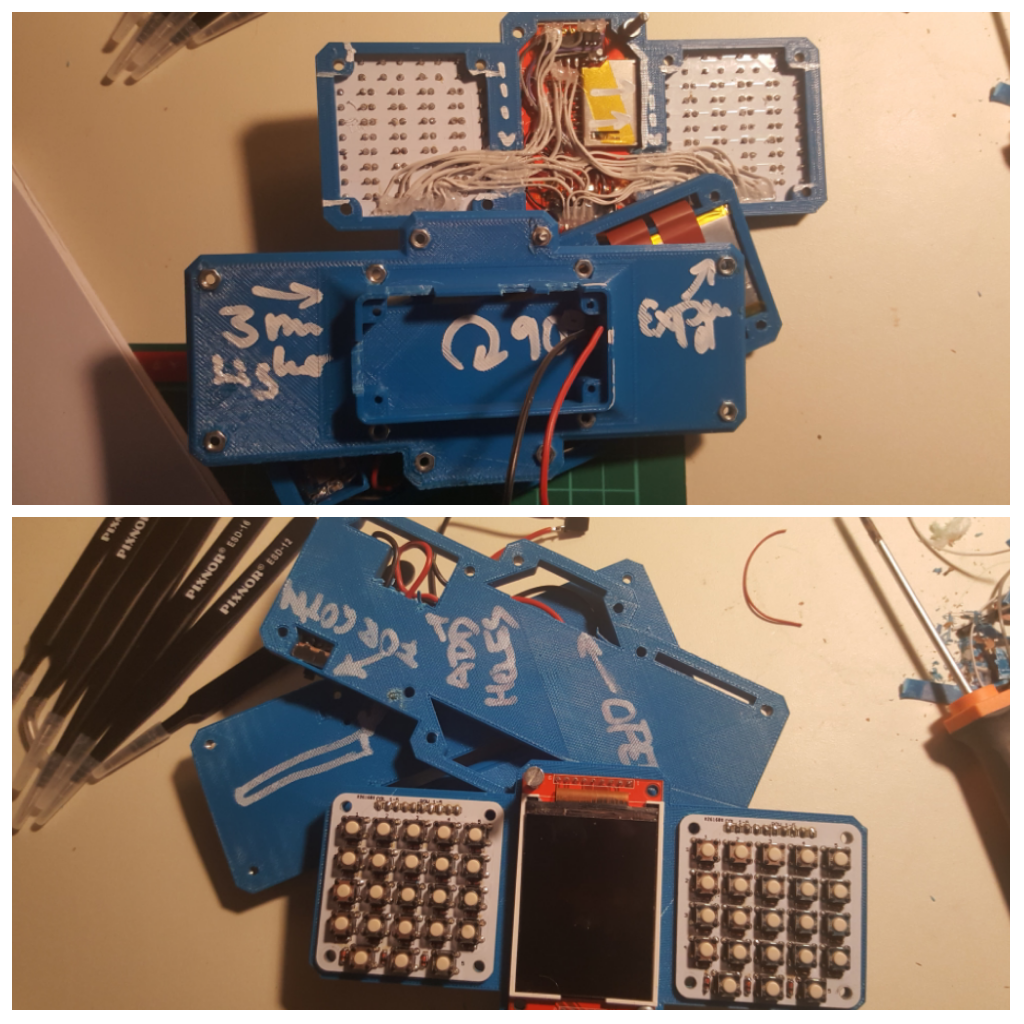
You can now download an print along :D only thing missing is the cover for the raspberry PI bottom. Notes came in handy.
Portable Raspberry PI Zero | Keyboard
2016-10-27 13:25:34
Wiring is done with the help of two PCF8574 I2C input expander. not sure if I'll write it with wiring or python or if i will use an external IC for scanning.


https://hackaday.io/page/2325-keyboards-please
you can read here how I got to the keyboard I designed.
Heimdall - dumb remote home | 3/4 connected
2016-10-23 16:18:22
so I'm able to ssh into 3/4 pi zeros, when the bridge is setup, but I can't get to PIzero4 - sooo annoying!
Heimdall - dumb remote home | and another one
2016-10-23 12:02:42
So this board is supposed to be a stamp "USB to testpoint" connector. But as soon as I ordered the thing I noticed it would totally make sense to add a mosfet for controlling power to it and maybe add the run pin and another dedicated pin for remote shutdown and remote reset. Ah well. Feels like midnight.

Heimdall - dumb remote home | TSSOP-30 breakout board for PCM1863
2016-10-23 00:50:18
not sure if it'll actually work, but to connect the PCM1863 and play around with it on the Raspberry PI, almost like this one, but backwards:
http://hackaday.com/2015/12/10/audio-streaming-on-the-cheap-with-an-rpi-zero/
I couldn't find any breakout boards for tssop30 and I had to design the footprint/part in eagle anyways, so this happend:

Heimdall - dumb remote home | guide
2016-10-22 22:46:55
http://raspberryjamberlin.de/zero360-part-2-connecting-via-otg-a-cluster-of-raspberry-pi-zeros-to-a-pi-3/
This is basically what I'm following to set up the cluster. Meh, so much for me doing the hard work :D Every SD card is flashed on configured (at least that what I hope).
I'm waiting for the currently printing 4th version of my minimal cluster holder.
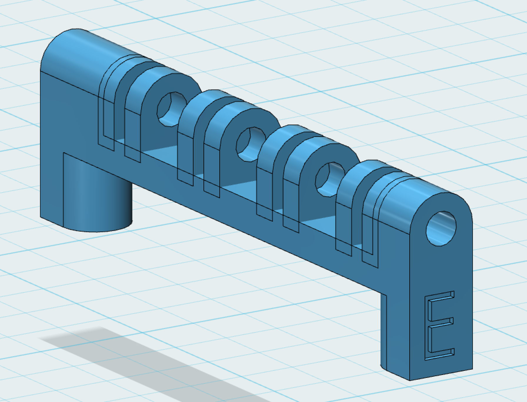
I think I have the center of the usb plugs and and everything else right, now. This will integrate fine into my cluster build. I've added Letters for USB and Ethernet to not confuse orientation. The SD cards all have to point in the same direction, imo.
The only thing annoying me at the moment is the usb cable management. A self made 4port usb to 4 single micro usb plugs is in development, but for now I use the Anker 15cm cables. There's definitely room for improvement.
For better fitting an angled network cable should be acquired as well :D
I'm still too much of a wuss to solder the usb ports directly and I wan't a clean looking build.
Hey Dusan
2016-10-16 11:30:43
please check both links in your feed and tell me if both link to the page like I said it would not. @Dusan Petrovic
Heimdall - dumb remote home | case redesign and contest goals
2016-10-15 23:46:19
This is my newest attempt on a mac pro inspired design, but this time it's supposed to fit the pi zero cluster. I'm going to make a special usb cable with angled connectors and a self made 2x2 usb connector. The holder for the pi zeros is the third version I'm printing right now. There is a 5x5cm fan planned and also a "16bit" neopixel ring. So this has all the stuff for a rage-filled-comment-filling blog entry:
- too many Raspberry PI zeros nobody gets
- an ineffective cluster not worth the money for a cluster
- a 3D printed case printed with a printer nobody wants to pay for
- a fan on a Raspberry PI
- too many blinking lights, possibly controlled by an arduino
So this is what I'm trying to do for the contest:
- Get the cluster going
- finish a case and make it free / downloadable
- run alexa services