I placed the breadboard upside down by accident. Here is a shaky video of the prototype.
| 2026 | 2024 | 2023 | 2022 | 2021 | 2020 | 2019 | 2018 | 2017 | 2016 | 2015 | 2014 |
|---|---|---|---|---|---|---|---|---|---|---|---|
| 2 | 2 | 11 | 15 | 23 | 13 | 30 | 72 | 152 | 102 | 134 | 62 |
I placed the breadboard upside down by accident. Here is a shaky video of the prototype.
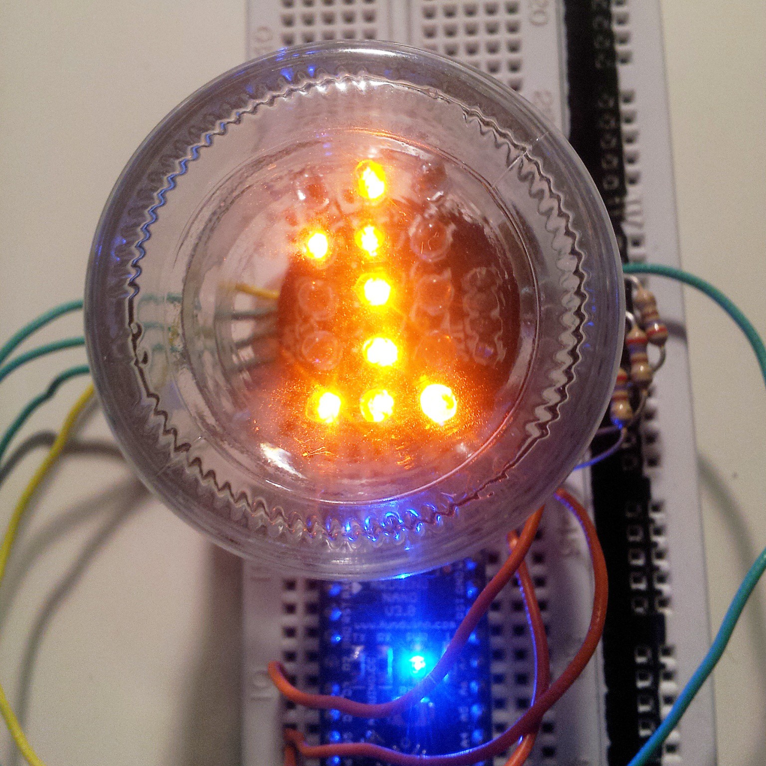
I soldered 15 LEDs today, and I soldered them backwards. I wonder how and why this is always happening to me, but I guess that is due to my laziness to check my own sketches... nevermind, some arduino code later I had this little mockup prepared. You can still see the board behind it, but as soon as the base plates arrive, it will be a lot darker in the background and the blue LEDs for the boarder will distract you from the background even more, I'm quite pleased with the outcome so far. The LEDs are actually glowing more orange than on this picture.
The LEDs I ordered as seen in the picture are orange but I may use amber colored LEDs I still have laying around. I previously ordered new LEDs because I had not enough for 6 displays but looking at the orange I'm not sure I'm satisfied. To be sure I should build a second one with the amber LEDs and compare them directly.
I'm still waiting for the control boards and the blue LEDs. After that I have to design and print the jar sockets
Since mr.jb.swes project Multicharger is all over my feed, hackaday.com (congrats!) and this page too, I'm thinking far ahead of my timeline. To keep it simple I want a single cell setup, boosting the voltage up to 5V. The hall effect sensors are only working with 5V so I started my first compromise, which turned out to be good, because this way I can monitor the power from the cell with an analog in pin of the arduino and everything gets more tinkerer-friendly. Now I need a way to get the dynamo voltages down to 3.5V to charge the LiFePo accordingly. Sounds overly complicated to convert from 6V to 3.5V to 5V but a battery comes in handy when you are standing because of a traffic light in the nights and you don't want your lights (or computer) to go off.
it's not much right now, but here is my sketch repo
https://github.com/davedarko/OpenBikeComputer
I will add this in the links, too.
So I forgot how I wanted to control the arrays with the 74hc595 but I guess it doesn't matter too much since I wanted to light max 3 leds at a time. I may turn the boards upside down because of the silkscreen.

The software so far can be seen in this video log I made. I kind of have this annoying bored-sounding, really slow voice on videos, sorry for that :D I'm really thinking while talking since I'm not a native speaker.
Today I received the I2C OLED display and the first thing I wanted to do was creating an I2C/IIC display header for it. Going through many tutorials I started my own library today with my first entry; the IIC display thin.


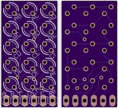
Yesterday I was chasing duo/bicolor LEDs on ebay.com because I read about blue/red ones on Reactron Integron for Automobile from Kenji Larsen. It never occurred to me that they weren't only red/green ones anymore. Inspired by this I made a 3x5 (15) LED matrix board with charlieplexed pinout in the hope I will be able to make a sometimes purple/red/blue display or colored temperature thingy. This will give me some coding experience since I have to come up with some array magic. I still haven't found out how I can tent the vias in eagle so OSHpark will add the solder stop mask over. The next iteration will probably have 1206 resistors on there and after that I'm going to order the 11*10 matrix I have already designed. This big matrix is perfect for a word clock project but I would need to check my software before. I'm also interested in a clock design as supposed to be seen here: http://hackaday.io/project/1480-Charlieplexed-LED-Clock this would need 9*8 (72) pins (60 for minutes and 12 for the hours) and a good positioning/addressing system.
Awesome links
https://dl.dropboxusercontent.com/u/4345112/www/mrule/charlymuxing/charliemux.html
http://tomscircuits.blogspot.de/2010/10/charlie-cube.html
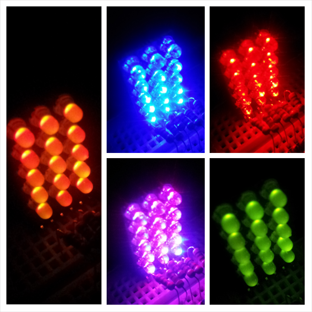
[UPDATE] Final results
I had to solder two jumper wires to make the connections to fix the somewhat buggy display, but now it's all worked out :) I bought red-blue and red-green BI/Duo LEDs.
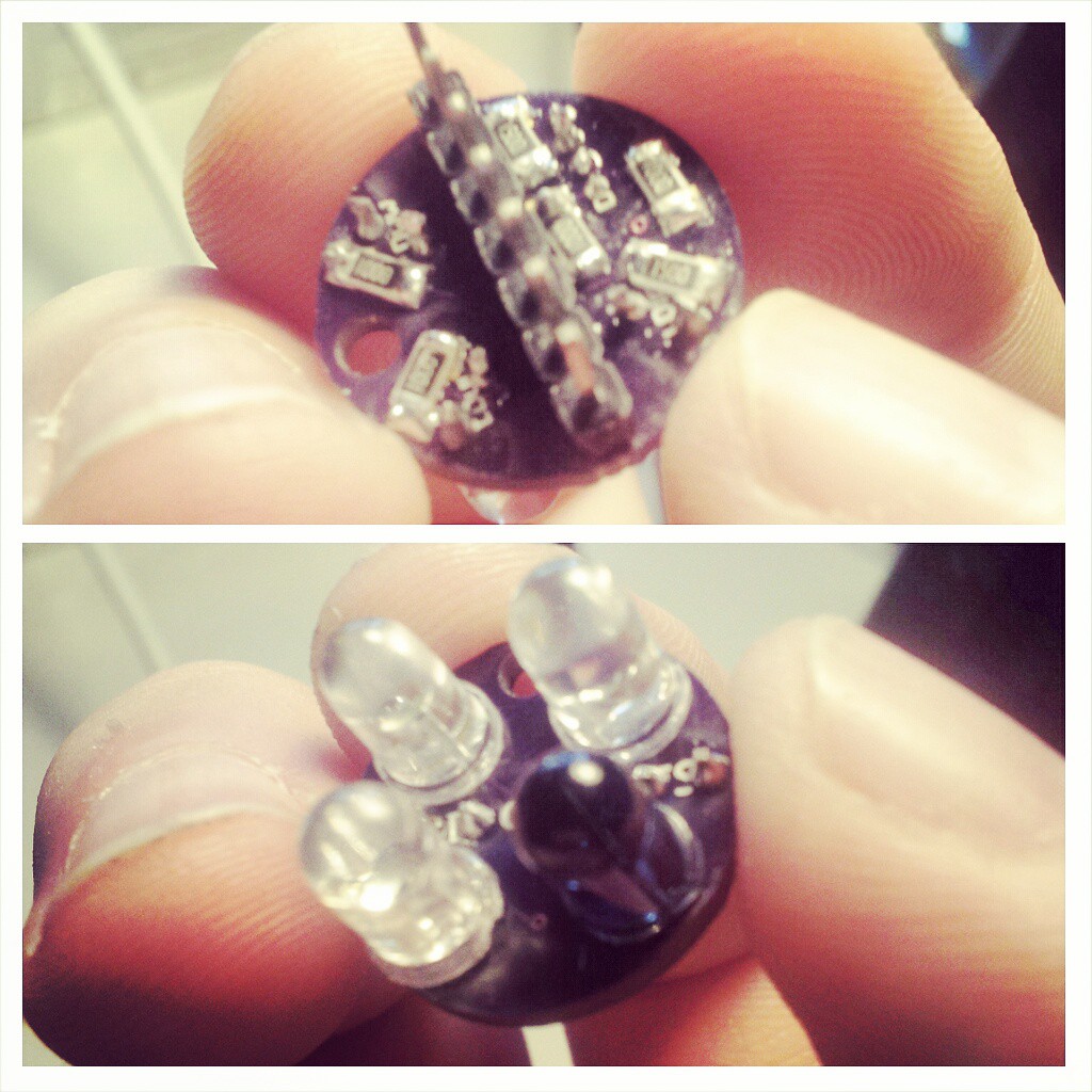
Today I overcame my frustration with the connectors that were too small and had all the parts present to solder the first dome. I had to file the rgb LED legs down so that they would be thin enough to fit the holes. The IR led had very thick spacers that had to go too.
The next pcb is already designed and ordered. It is merely an adapter board and holder of a 3mm photodiode that will have 4 1x2 pin header going to the next board
I remembered that IKEA has those metal boxes named SNIKA which would be a really cool casing for a bigger project. With that in mind I found FINTORP while looking for green storage parts, because I could not remember the name before. Green is also a repeating color in my room and the military touch for this project is fine too. I plan on using the open side as the clock display side. 3D printed sockets for the tubes and a guide to slide in the main pcb will assist the faceplate to interlock with the case.
UPDATE 17.07.2014
So today I was at IKEA and the GRUNDTAL was the final candidate when I noticed that the FINTORP was way too big for my desk and in relation to my fixie tubes.
So the LED boards came in yesterday and my bad luck with ordered pcbs seem to continue - the footprint of the RGB LED is to small! I guess that is somewhat the mistake of the user who made the part and the crux of 123d.circuits.io - nobody checks your work. Carefully drilling the holes bigger could work, but my drill bits are all broken and I have to wait for the 150Ohm smd resistors.
Since the atmega328 current per pin is about 40mA I think I will drop the ULN2803 for now and focus on the main board with the linear potentiometer and the led display and finally get a decent case and the power setup done.
I also started a nice little distraction - LED nixie tubes http://hackaday.io/page/436
So I took my bicycle out to my parents, about an hour ride and I noticed that it's quite embarrassing as a tinkerer not having my own arduino based bycicle computer. I've looked around the web and could not find something satisfying to start with, only a youtube video
The software seems to be a good starting point, but it's not complete and the hardware lacks at least a case and a pcb. So right now i'm collecting things one could do with an arduino based bycicle computer. Which information is relevant for me, what should it at least do, what could be nice to have etc.
don't feed or order them at night. So the boards for the shield came in today and I placed all the parts facing towards the arduino board instead and missed connecting almost everything with vcc. It's all connected with each other, but not with vcc :D Luckily I can fix this with a jumper wire and turn everything upside down, put the dip switches on top of the smd resistors. I'm missing pin connectors to try complete the shield, so i'm ordering these and keep it in the box until arrival.. Normally I love those purple boards, but the leds and blue dip switches are hurting my eyes.

I just thought about turning a rubik cube into an interface or lock by using 6 encoders as a way to grab the rotation and send those inputs to an rgb 3x3x3 cube or 8x8x8 rgb locomatrix, when ready ;) I'm still sidetracked by my continuum quantum device prop build, repairing and upgrading my printrbot simple and work of course but always try to come up how to integrate functions and interfaces into props and things laying around.
Googe found me this:
http://www.fastcodesign.com/1671039/a-music-making-interface-that-riffs-on-the-rubik-s-cube
Ha, and this, so I'm not the first - good!
http://www.3ders.org/articles/20131206-transform-an-entire-building-into-a-playable-rubik-cube.html
The community voting today alarmed me to finally put in a contest entry to have at least a glance at winning something. This doesn't feel like the best choice for the contest to win it, but I could not come up with something really good "connected thing" and didn't want to start a new project so I felt the best would be to pick an existing. Let me go through the pros and cons of my projects.
---------- more ----------Towani Lifesign Device
[http://hackaday.io/project/616-Towani-Lifesign-Wristdevice---Star-Wars-Ewoks]
it would be interesting enough to put this to a next level by connecting it to the internet somehow, since its health related and has a social component as well. But it's not unique and not my Idea in the first place - you've seen it in star wars. Sounds like way too much trouble to get the licenses.
Sonic Screwdriver
[http://hackaday.io/project/972-Sonic-Screwdriver]
The same here for the licenses since BBC and Doctor Who are a big number and frankly my sonic is a colored flashlight with annoying sounds and a 433MHz transmitter. Why would I connect that with anything.
Locomatrix 3D POV
[http://hackaday.io/project/1148-Locomatrix---3D-POV---a-different-approach]
So here we are, my contest entry. It is a unique way to display three dimensional data with LEDs. I'm able to display N x 8x8 datasets where N is limited by the interval I divide the z-axis. It's not a prop I put some LEDs and an arduino in. It's my design I put some LEDs and an arduino in ;) I'm gonna find something useful to show on my display, may be the weather forecast or depth scanner output device. Any ideas are welcome.
I recently got distracted from everything when I saw a quantum device from the canadian show "continuum" on thingiverse.com and had to make my own version of it, because I wasn't happy with the file someone uploaded. So I made this; 8 different parts, holes for magnets for the snapping effect, researched wobble positions.
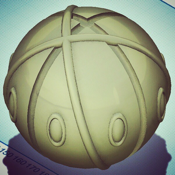
http://www.thingiverse.com/thing:365370
I have printed 6 1/2 parts right now. My printrbot simple intends to shift sometimes on the x axis so I had to stop the print and rip of the layers printed wrong. By printing the top half of the part and hot-glueing them together I'm going to save about 4 meters of plastic I would have to throw away. By extruding PLA manually I can easily fix holes and gaps in the parts and it worked before. It would be cool to have a beacon activated when all the parts are put together.
Hardware
Today I finally ordered the LED dome board from circuits.io - I wanted to rebuild that with eagle but got frustrated with the available pinheaders and thought the time I would spend to create my own wasn't worth the 5usd I would save so what the heck. The other boards will be done in eagle, especially an arduino-a-like board as the mainboard.
Software
on the software side hasn't happen that much, I wrote a BPM clicker for it and a DAZZLER program, where the LEDs blink randomly as seen on hackaday.com http://hackaday.com/2009/09/28/open-source-weapon-makes-you-puke/
Yesterday i spent 5hours fixing my printrbot simple so I could go on my self with the gearbox and the new motor. I got almost the same motor speed as before with no smoking motors. But this time I blew off a capacitor on an arduino by not giving attention to the poles. Gladly I was able to rip it off and place a new cap on there. I still have to use a motor bridge or a pwm control.
---------- more ----------So here are some pictures of the gears I imported from svgs me and someone on wikipedia did.

And the spacer for the gears. I think I have to reprint it though and make it almost closed on one side, so only the 4 toothed gear will stick out.

I used my soldering iron for welding.

So since my leds came in I wanted to work on this a bit and decided to design a shield for my atmega8 boards and let the leds glow with a software pwm and work on the transmission protocols.

So i won a fubarino on hackaday a while ago and still haven't figured out what I should or could do with that thing. It's calling for something awesome but my head is full of blinking leds right now... I never really reached the constraints of an arduino with an atmega328, so I'm asking for ideas.