LED displays on Arduinos - a collection | Arduino Pro Mini - 8x8 DIY matrix - Version 2
2016-10-14 11:44:30
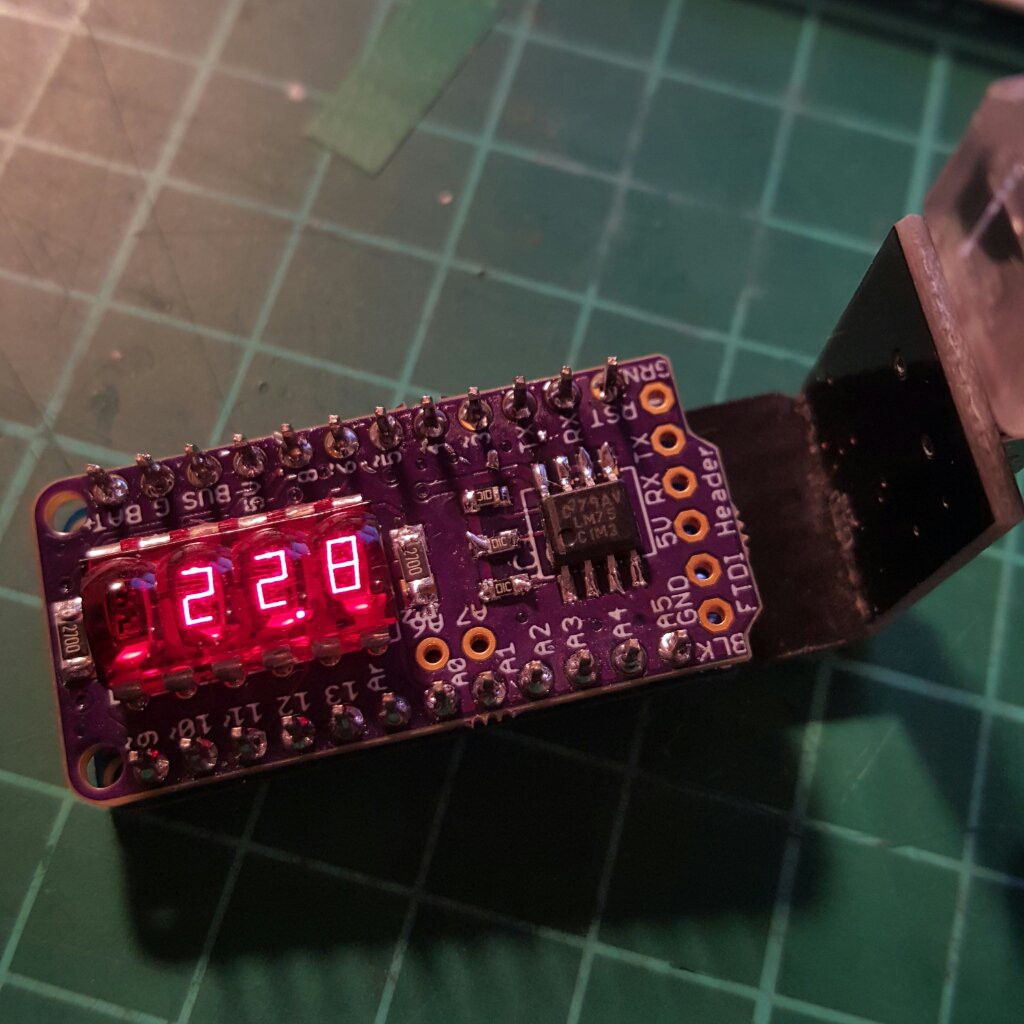
I used some sanding paper to diffuse the displays but stripped of the grey stuff as well. still looks nice though. It's possible to daisy them with I2C and put them next to each other to get an even bigger matrix. Works as a micro badge.
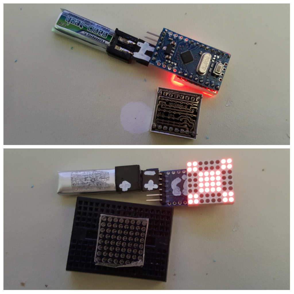
Here's the pinout of those tiny matrices. Had to google the name on the PCB to find stuff. Funky trap when checking the pinouts, it's not like an IC where the first row - first col LED is on the top left, it's on the bottom.
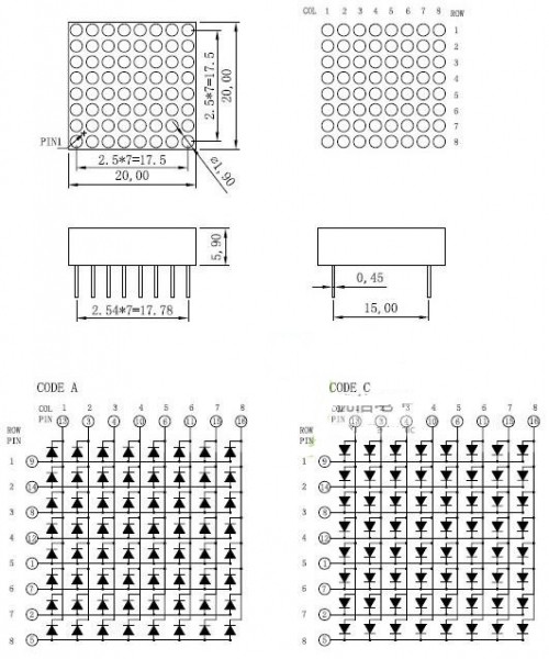
Here's some code to start:
int col_pins[8] = {
5, A1, A0, 8, 12, 7, 3, 2
};
int row_pins[8] = {
9, 4, 10, 6, A3, 11, A2, 13
};
byte img[8] =
{
B11000011,
B11000011,
B00111100,
B00111100,
B00111100,
B00111100,
B11000011,
B11000011
};
void setup() {
for (int i=0; i<8; i++)
{
pinMode(col_pins[i], OUTPUT);
pinMode(row_pins[i], OUTPUT);
}
for (int i=0; i<8; i++)
{
digitalWrite(col_pins[i], HIGH);
digitalWrite(row_pins[i], LOW);
}
}
void loop()
{
for (int j=0; j<8; j++)
{
digitalWrite(col_pins[j], LOW);
int i = 0;
for (byte mask = B00000001; mask>0; mask <<= 1)
{
if (img[j] & mask)
{
digitalWrite(row_pins[i], HIGH);
delayMicroseconds(15);
digitalWrite(row_pins[i], LOW);
delayMicroseconds(5);
}
else
{
digitalWrite(row_pins[i], LOW);
delayMicroseconds(20);
}
i++;
}
digitalWrite(col_pins[j], HIGH);
}
}
https://cdn.hackaday.io/images/3990331476437873048.png
https://cdn.hackaday.io/images/2189991476437733925.jpg
LED displays on Arduinos - a collection | Arduino Pro Mini - 8x8 DIY matrix - Version 2
2016-10-14 11:44:30
I used some sanding paper to diffuse the displays but stripped of the grey stuff as well. still looks nice though. It's possible to daisy them with I2C and put them next to each other to get an even bigger matrix. Works as a micro badge.
Here's the pinout of those tiny matrices. Had to google the name on the PCB to find stuff. Funky trap when checking the pinouts, it's not like an IC where the first row - first col LED is on the top left, it's on the bottom.
Here's some code to start:
int col_pins[8] = {
5, A1, A0, 8, 12, 7, 3, 2
};
int row_pins[8] = {
9, 4, 10, 6, A3, 11, A2, 13
};
byte img[8] =
{
B11000011,
B11000011,
B00111100,
B00111100,
B00111100,
B00111100,
B11000011,
B11000011
};
void setup() {
for (int i=0; i<8; i++)
{
pinMode(col_pins[i], OUTPUT);
pinMode(row_pins[i], OUTPUT);
}
for (int i=0; i<8; i++)
{
digitalWrite(col_pins[i], HIGH);
digitalWrite(row_pins[i], LOW);
}
}
void loop()
{
for (int j=0; j<8; j++)
{
digitalWrite(col_pins[j], LOW);
int i = 0;
for (byte mask = B00000001; mask>0; mask <<= 1)
{
if (img[j] & mask)
{
digitalWrite(row_pins[i], HIGH);
delayMicroseconds(15);
digitalWrite(row_pins[i], LOW);
delayMicroseconds(5);
}
else
{
digitalWrite(row_pins[i], LOW);
delayMicroseconds(20);
}
i++;
}
digitalWrite(col_pins[j], HIGH);
}
}
https://cdn.hackaday.io/images/3990331476437873048.png
https://cdn.hackaday.io/images/2189991476437733925.jpg