I want something usb stick thingy-ish to check a usb cable A little ATtiny45, some LEDs and transistors - battery powered. It scans through the cable with some blinking LEDs, then goes to sleep.
USB cable tester | New Revision
2021-07-19 00:35:03
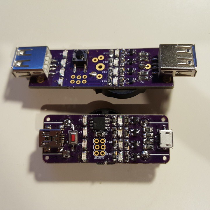
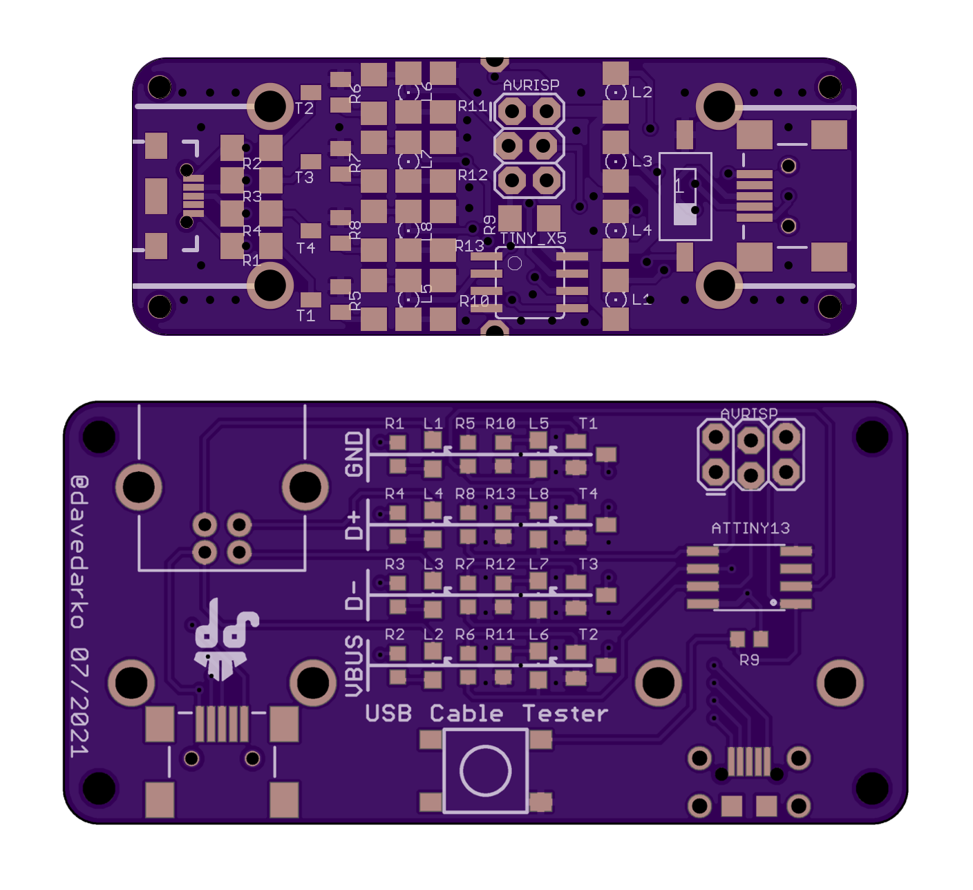
Today I went sorting through some USB cables, but before I could test anything, I had to solder the third and last of the boards that I had ordered years ago. The micro-B USB socket held for 15 cables before I had to add glue because it got loose [log for board 2]. So I decided to update some parts on the PCB and shift things around.
USB-A + micro/mini Sockets are turned 90 degrees, so you can test shorter cables
additional USB-B connector so you can test A-B cables
button is now a 6mm x 6mm sized one
LEDs all point in the same direction and are marked, good for soldering