Ignore this ESP8266 board
I stole from every one. The huzza from Adafruit. Matts breakout board. Al1s board from here. NodeMCUs DevKit.
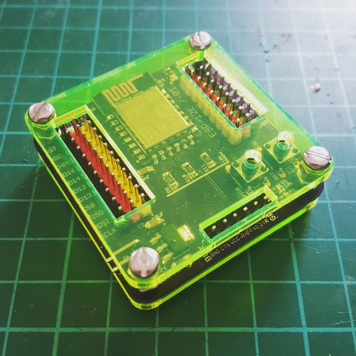
This will be my first http://dirtypcbs.com/ order and since I have ESP-01 and ESP-12 I wanted to have a board that could take them both. I fell in love with GVS rails when I saw them on someones project here. This board follows the usual rules:
Keep GPIO15 LOW (why did they even break it out in the first place?)
Keep GPIO2 HIGH (I've seen it everywhere but some do not specifically say that)
You could also get rid of the reset button, when you just unplug the thing and hit GPIO0 on plugging it back in (HIGH is RUN and LOW is FLASH).
Watch out for the ADC, MAX is 1V (not 1.8V as stated before). That's why I've added a voltage divider.
LED is on GPIO0 now!
There is no extra serial/usb thing on it, cause it would have added extra costs and for experiments it's okay to use a dongle and finished projects wouldn't need programming anyway.
Ignore this ESP8266 board | using the ADC with the arduino IDE
2015-12-04 20:35:22
I've changed the two ADC resistors to 10k and 3.9k, giving me a range of 0V - 4.9V to be able to check the battery connected to the system.
Here's a little conversion script for reading and printing the values. I'm high on sugar, so it took me longer than I am able to admit :D
int r1 = 3883;
int r2 = 1000;

void setup() {

  Serial.begin(9600);
}

void loop() {
  float val = analogRead(A0);

  float vout = (val) * (r1 + r2) / r2 / 1023;
  Serial.print(val);
  Serial.print(" - ");
  Serial.println(vout);
  delay(200);
}