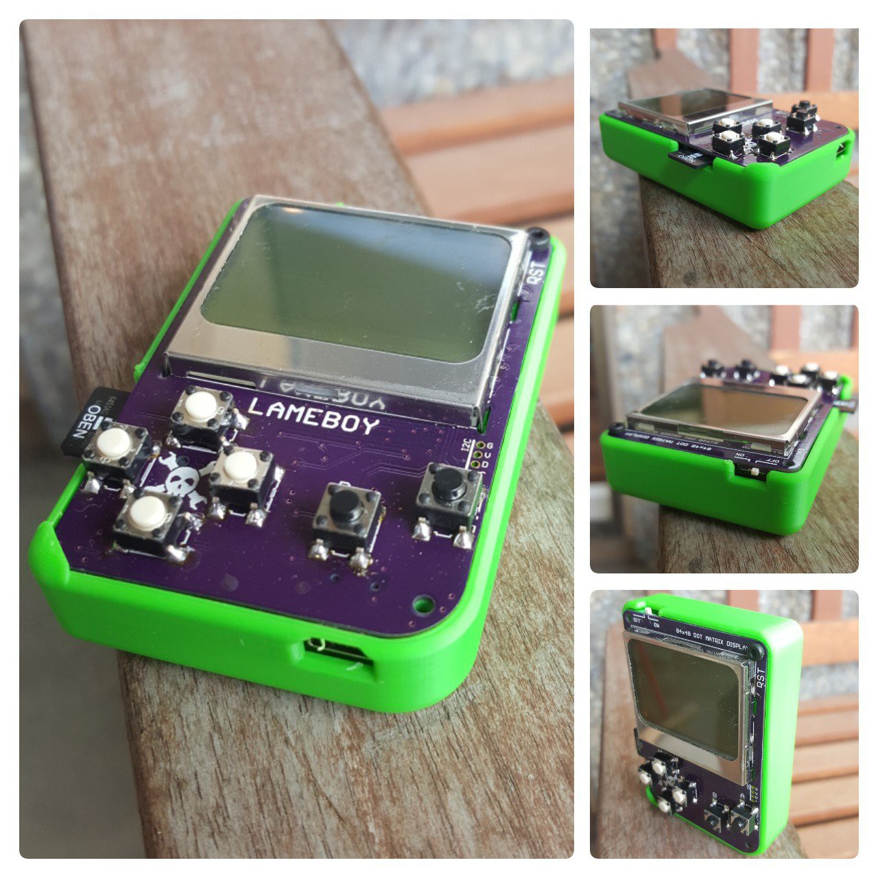
LAMEBOY - another ESP12 handheld
fully portable ESP12 project with battery charging and power muxing
Ever since
https://hackaday.io/project/18648-nokia-3310-5110-display-board I've wanted to slap on an ESP module and some buttons to make a nice little portable handheld. Now with some googling and checking out other projects how they get their stuff done and a bit time on hand while on vacation I'm using every spare minute to work on this PCB. There are some minor things I'm not sure about that need testing, but the general concept is clear.
LAMEBOY - another ESP12 handheld | Deauther ordeal
2020-08-24 21:12:14
I finally found my 2017 modified version of the deauther and added it to the download section. Use at own risk, don't come to me or Spacehuhn for advice. This is as is. Use it on your own tech only. Don't make people hate you because you want to "jam" your neighbors. Be nice and responsible.
Proud of the added "scan" for the button IO expander, as I've used different versions with different addresses over time.