PCB word clock | Version One :)
2017-02-17 03:06:21
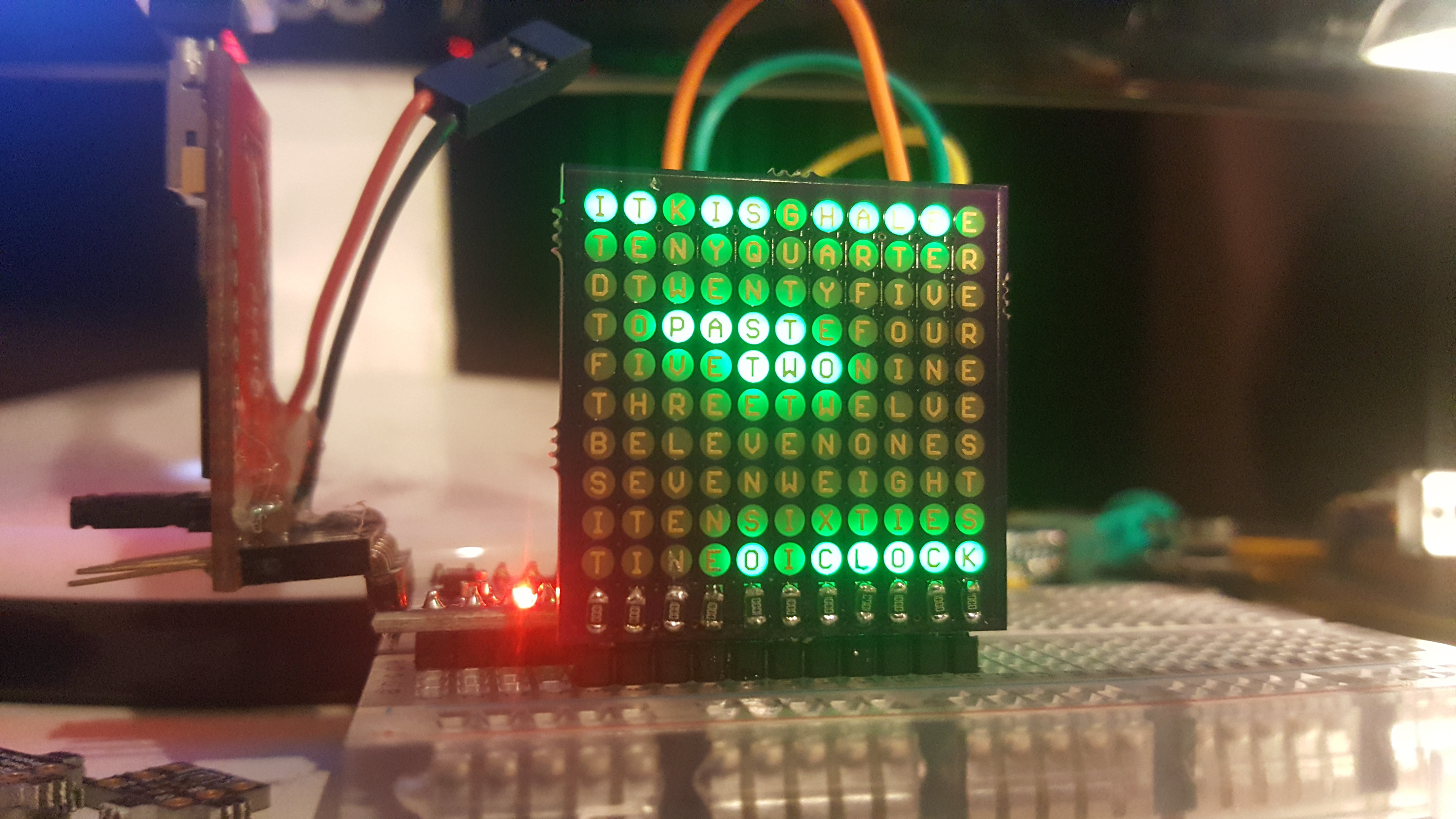
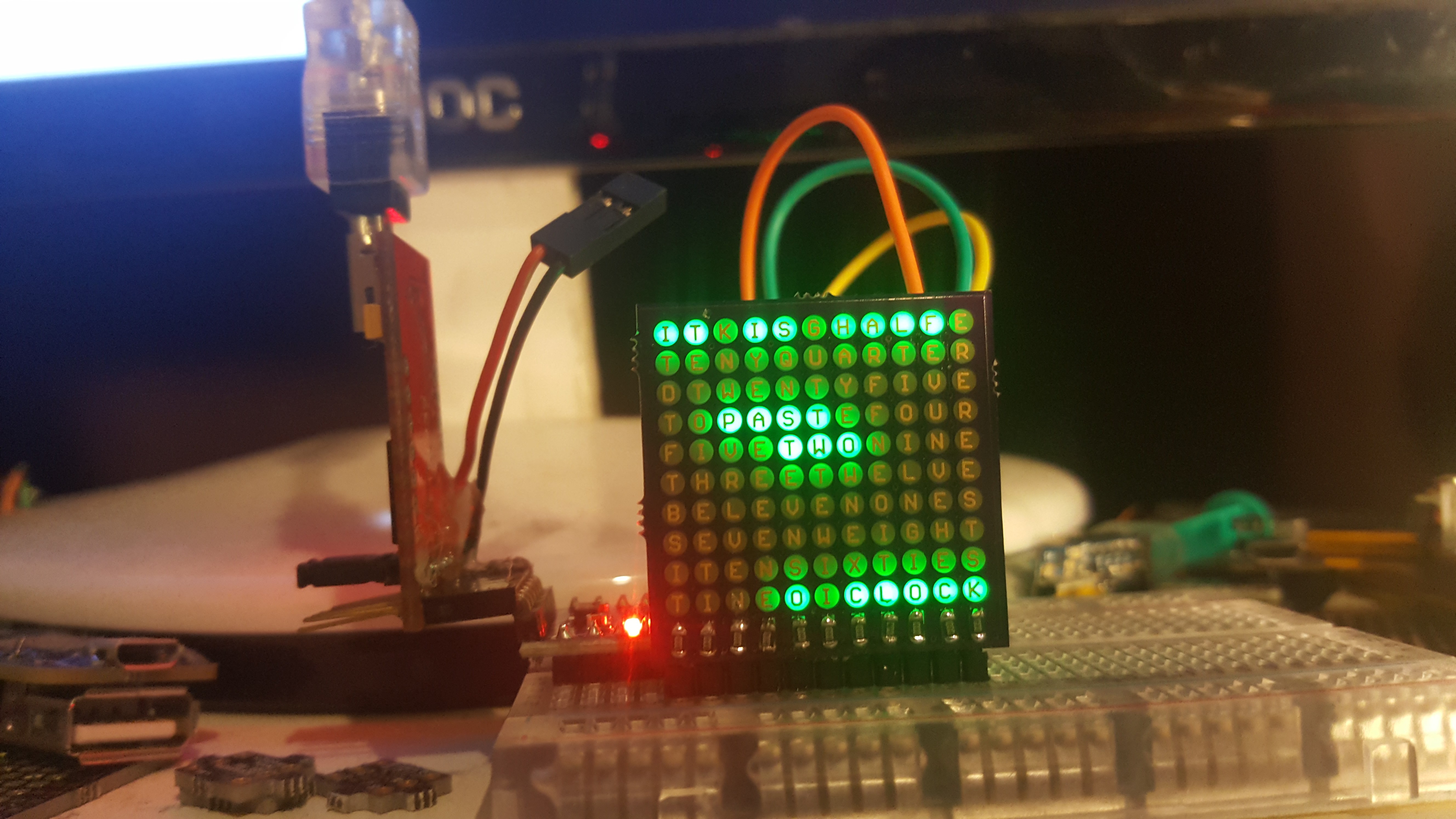
Update fun fact: analyzing a charlie plexed matrix for bugs is so much easier when the LEDs are upside down - because of the markings :)
I finally got my LEDs and took the time to hand solder a PCB :) it bleeds a bit in the picture, but in real life it's quite good. The code so far is only a mock up, but there is scanning and matrix stuff involved already.
#include <avr/pgmspace.h>
const int leds[] = {2,3,4,5,6,7,8,9,10,11,12,13};
const int matrix[10][11][2] = {
{ {1, 0}, {0, 1}, {0, 2}, {0, 3}, {0, 4}, {0, 5}, {0, 6}, {0, 7}, {0, 8}, {0, 9}, {0, 10} },
{ {2, 0}, {2, 1}, {1, 2}, {1, 3}, {1, 4}, {1, 5}, {1, 6}, {1, 7}, {1, 8}, {1, 9}, {1, 10} },
{ {3, 0}, {3, 1}, {3, 2}, {2, 3}, {2, 4}, {2, 5}, {2, 6}, {2, 7}, {2, 8}, {2, 9}, {2, 10} },
{ {4, 0}, {4, 1}, {4, 2}, {4, 3}, {3, 4}, {3, 5}, {3, 6}, {3, 7}, {3, 8}, {3, 9}, {3, 10} },
{ {5, 0}, {5, 1}, {5, 2}, {5, 3}, {5, 4}, {4, 5}, {4, 6}, {4, 7}, {4, 8}, {4, 9}, {4, 10} },
{ {6, 0}, {6, 1}, {6, 2}, {6, 3}, {6, 4}, {6, 5}, {5, 6}, {5, 7}, {5, 8}, {5, 9}, {5, 10} },
{ {7, 0}, {7, 1}, {7, 2}, {7, 3}, {7, 4}, {7, 5}, {7, 6}, {6, 7}, {6, 8}, {6, 9}, {6, 10} },
{ {8, 0}, {8, 1}, {8, 2}, {8, 3}, {8, 4}, {8, 5}, {8, 6}, {8, 7}, {7, 8}, {7, 9}, {7, 10} },
{ {9, 0}, {9, 1}, {9, 2}, {9, 3}, {9, 4}, {9, 5}, {9, 6}, {9, 7}, {9, 8}, {8, 9}, {8, 10} },
{ {10, 0}, {10, 1}, {10, 2}, {10, 3}, {10, 4}, {10, 5}, {10, 6}, {10, 7}, {10, 8}, {10, 9}, {9, 10} }
};
const boolean img [10][11] = {
{ true, true, false, true, true, false, true, true, true, true, false},
{false, false, false, false, false, false, false, false, false, false, false},
{false, false, false, false, false, false, false, false, false, false, false},
{false, false, true, true, true, true, false, false, false, false, false},
{false, false, false, false, true, true, true, false, false, false, false},
{false, false, false, false, false, false, false, false, false, false, false},
{false, false, false, false, false, false, false, false, false, false, false},
{false, false, false, false, false, false, false, false, false, false, false},
{false, false, false, false, false, false, false, false, false, false, false},
{false, false, false, false, true, false, true, true, true, true, true},
};
void setup() { }
void loop() {
for (int y=0; y<10; y++)
{
for (int x=0; x<11; x++)
{
if (img[y][x]) charlie_matrix (x, y);
}
}
}
void charlie_matrix (int x, int y)
{
int cx = matrix[y][x][0];
int cy = matrix[y][x][1];
digitalWrite(leds[cx], LOW);
pinMode(leds[cx], OUTPUT);
digitalWrite(leds[cy], HIGH);
pinMode(leds[cy], OUTPUT);
delayMicroseconds(65);
pinMode(leds[cx], INPUT);
digitalWrite(leds[cx], LOW);
pinMode(leds[cy], INPUT);
digitalWrite(leds[cy], LOW);
delayMicroseconds(5);
}https://cdn.hackaday.io/images/2120051487297085481.jpg
PCB word clock | Version One :)
2017-02-17 03:06:21
Update fun fact: analyzing a charlie plexed matrix for bugs is so much easier when the LEDs are upside down - because of the markings :)
I finally got my LEDs and took the time to hand solder a PCB :) it bleeds a bit in the picture, but in real life it's quite good. The code so far is only a mock up, but there is scanning and matrix stuff involved already.
#include <avr/pgmspace.h>
const int leds[] = {2,3,4,5,6,7,8,9,10,11,12,13};
const int matrix[10][11][2] = {
{ {1, 0}, {0, 1}, {0, 2}, {0, 3}, {0, 4}, {0, 5}, {0, 6}, {0, 7}, {0, 8}, {0, 9}, {0, 10} },
{ {2, 0}, {2, 1}, {1, 2}, {1, 3}, {1, 4}, {1, 5}, {1, 6}, {1, 7}, {1, 8}, {1, 9}, {1, 10} },
{ {3, 0}, {3, 1}, {3, 2}, {2, 3}, {2, 4}, {2, 5}, {2, 6}, {2, 7}, {2, 8}, {2, 9}, {2, 10} },
{ {4, 0}, {4, 1}, {4, 2}, {4, 3}, {3, 4}, {3, 5}, {3, 6}, {3, 7}, {3, 8}, {3, 9}, {3, 10} },
{ {5, 0}, {5, 1}, {5, 2}, {5, 3}, {5, 4}, {4, 5}, {4, 6}, {4, 7}, {4, 8}, {4, 9}, {4, 10} },
{ {6, 0}, {6, 1}, {6, 2}, {6, 3}, {6, 4}, {6, 5}, {5, 6}, {5, 7}, {5, 8}, {5, 9}, {5, 10} },
{ {7, 0}, {7, 1}, {7, 2}, {7, 3}, {7, 4}, {7, 5}, {7, 6}, {6, 7}, {6, 8}, {6, 9}, {6, 10} },
{ {8, 0}, {8, 1}, {8, 2}, {8, 3}, {8, 4}, {8, 5}, {8, 6}, {8, 7}, {7, 8}, {7, 9}, {7, 10} },
{ {9, 0}, {9, 1}, {9, 2}, {9, 3}, {9, 4}, {9, 5}, {9, 6}, {9, 7}, {9, 8}, {8, 9}, {8, 10} },
{ {10, 0}, {10, 1}, {10, 2}, {10, 3}, {10, 4}, {10, 5}, {10, 6}, {10, 7}, {10, 8}, {10, 9}, {9, 10} }
};
const boolean img [10][11] = {
{ true, true, false, true, true, false, true, true, true, true, false},
{false, false, false, false, false, false, false, false, false, false, false},
{false, false, false, false, false, false, false, false, false, false, false},
{false, false, true, true, true, true, false, false, false, false, false},
{false, false, false, false, true, true, true, false, false, false, false},
{false, false, false, false, false, false, false, false, false, false, false},
{false, false, false, false, false, false, false, false, false, false, false},
{false, false, false, false, false, false, false, false, false, false, false},
{false, false, false, false, false, false, false, false, false, false, false},
{false, false, false, false, true, false, true, true, true, true, true},
};
void setup() { }
void loop() {
for (int y=0; y<10; y++)
{
for (int x=0; x<11; x++)
{
if (img[y][x]) charlie_matrix (x, y);
}
}
}
void charlie_matrix (int x, int y)
{
int cx = matrix[y][x][0];
int cy = matrix[y][x][1];
digitalWrite(leds[cx], LOW);
pinMode(leds[cx], OUTPUT);
digitalWrite(leds[cy], HIGH);
pinMode(leds[cy], OUTPUT);
delayMicroseconds(65);
pinMode(leds[cx], INPUT);
digitalWrite(leds[cx], LOW);
pinMode(leds[cy], INPUT);
digitalWrite(leds[cy], LOW);
delayMicroseconds(5);
}https://cdn.hackaday.io/images/2120051487297085481.jpg