hacking a smoke detector
adding an ESP-12 with some flipflop magic and MQTT
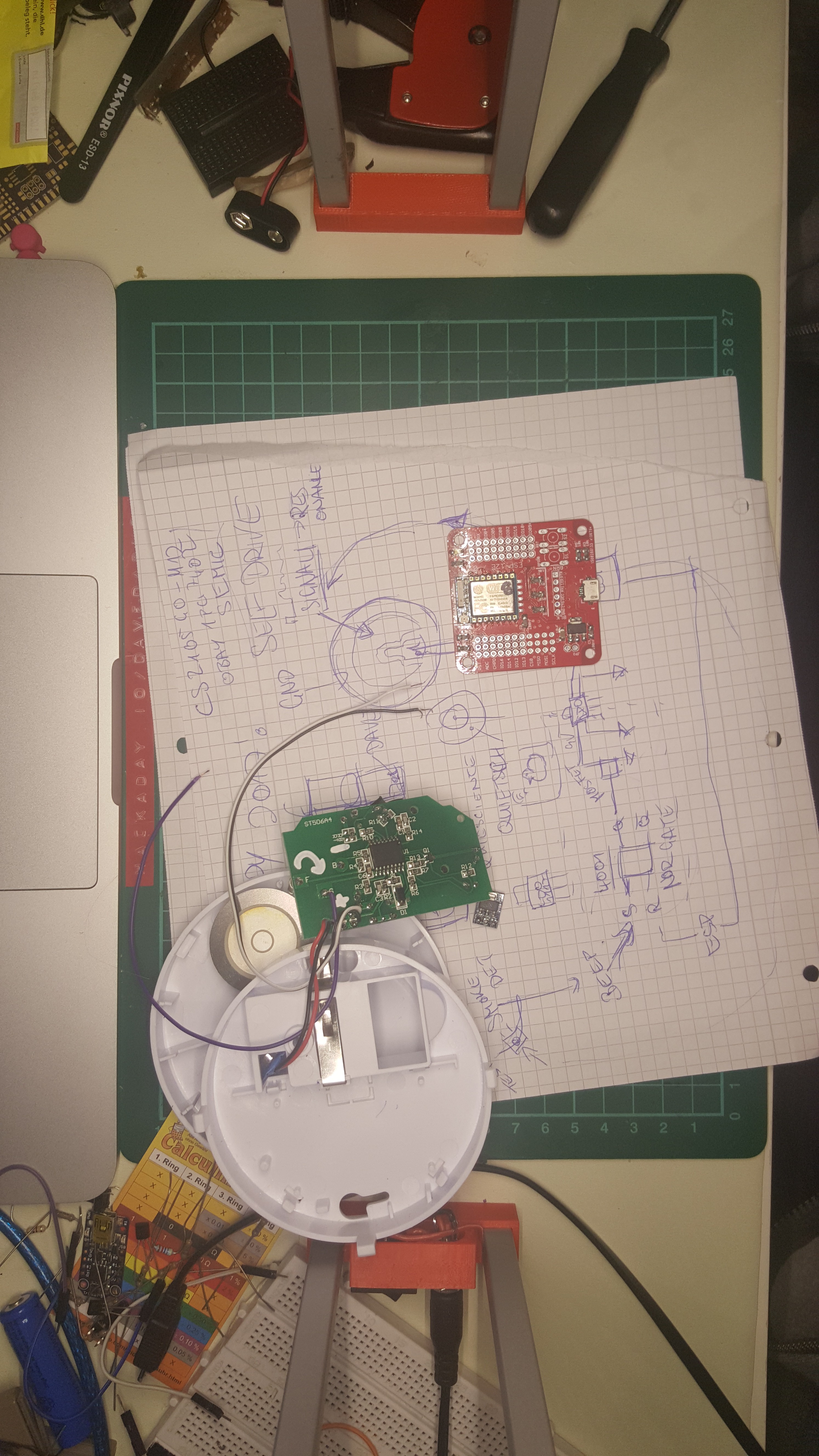
I started a youtube video for this but noticed that I need to plan this out more, or I will get 50min videos of me mumbling and rambling... so what's better than starting a project to organise your thoughts? This way I can also watch some editing tips videos on youtube.
This will touch thematics such as self drive piezos, logic gate, IoT stuff, powering things and MOSFETs. A lot to cover in a short video.
hacking a smoke detector | parts considerations
2017-08-19 11:23:00
http://www.ti.com/lit/ds/symlink/tpl5111.pdf 35nA thing that controls pwr converter and shutdown via gpio. only works with up to 5v though, not nine volt battery. so minimal power conversion still would be necessary.
hacking a smoke detector | parts considerations
2017-08-19 11:23:00
http://www.ti.com/lit/ds/symlink/tpl5111.pdf 35nA thing that controls pwr converter and shutdown via gpio. only works with up to 5v though, not nine volt battery. so minimal power conversion still would be necessary.
hacking a smoke detector | parts considerations
2017-08-19 11:23:00
http://www.ti.com/lit/ds/symlink/tpl5111.pdf 35nA thing that controls pwr converter and shutdown via gpio. only works with up to 5v though, not nine volt battery. so minimal power conversion still would be necessary.
hacking a smoke detector | parts considerations
2017-08-19 11:23:00
http://www.ti.com/lit/ds/symlink/tpl5111.pdf 35nA thing that controls pwr converter and shutdown via gpio. only works with up to 5v though, not nine volt battery. so minimal power conversion still would be necessary.
hacking a smoke detector | parts considerations
2017-08-19 11:23:00
http://www.ti.com/lit/ds/symlink/tpl5111.pdf 35nA thing that controls pwr converter and shutdown via gpio. only works with up to 5v though, not nine volt battery. so minimal power conversion still would be necessary.
hacking a smoke detector | parts considerations
2017-08-19 11:23:00
http://www.ti.com/lit/ds/symlink/tpl5111.pdf 35nA thing that controls pwr converter and shutdown via gpio. only works with up to 5v though, not nine volt battery. so minimal power conversion still would be necessary.
hacking a smoke detector | parts considerations
2017-08-19 11:23:00
http://www.ti.com/lit/ds/symlink/tpl5111.pdf 35nA thing that controls pwr converter and shutdown via gpio. only works with up to 5v though, not nine volt battery. so minimal power conversion still would be necessary.
hacking a smoke detector | parts considerations
2017-08-19 11:23:00
http://www.ti.com/lit/ds/symlink/tpl5111.pdf 35nA thing that controls pwr converter and shutdown via gpio. only works with up to 5v though, not nine volt battery. so minimal power conversion still would be necessary.
hacking a smoke detector | parts considerations
2017-08-19 11:23:00
http://www.ti.com/lit/ds/symlink/tpl5111.pdf 35nA thing that controls pwr converter and shutdown via gpio. only works with up to 5v though, not nine volt battery. so minimal power conversion still would be necessary.
hacking a smoke detector | parts considerations
2017-08-19 11:23:00
http://www.ti.com/lit/ds/symlink/tpl5111.pdf 35nA thing that controls pwr converter and shutdown via gpio. only works with up to 5v though, not nine volt battery. so minimal power conversion still would be necessary.
hacking a smoke detector | parts considerations
2017-08-19 11:23:00
http://www.ti.com/lit/ds/symlink/tpl5111.pdf 35nA thing that controls pwr converter and shutdown via gpio. only works with up to 5v though, not nine volt battery. so minimal power conversion still would be necessary.
hacking a smoke detector | parts considerations
2017-08-19 11:23:00
http://www.ti.com/lit/ds/symlink/tpl5111.pdf 35nA thing that controls pwr converter and shutdown via gpio. only works with up to 5v though, not nine volt battery. so minimal power conversion still would be necessary.
hacking a smoke detector | parts considerations
2017-08-19 11:23:00
http://www.ti.com/lit/ds/symlink/tpl5111.pdf 35nA thing that controls pwr converter and shutdown via gpio. only works with up to 5v though, not nine volt battery. so minimal power conversion still would be necessary.
hacking a smoke detector | parts considerations
2017-08-19 11:23:00
http://www.ti.com/lit/ds/symlink/tpl5111.pdf 35nA thing that controls pwr converter and shutdown via gpio. only works with up to 5v though, not nine volt battery. so minimal power conversion still would be necessary.
hacking a smoke detector | parts considerations
2017-08-19 11:23:00
http://www.ti.com/lit/ds/symlink/tpl5111.pdf 35nA thing that controls pwr converter and shutdown via gpio. only works with up to 5v though, not nine volt battery. so minimal power conversion still would be necessary.
hacking a smoke detector | parts considerations
2017-08-19 11:23:00
http://www.ti.com/lit/ds/symlink/tpl5111.pdf 35nA thing that controls pwr converter and shutdown via gpio. only works with up to 5v though, not nine volt battery. so minimal power conversion still would be necessary.
hacking a smoke detector | parts considerations
2017-08-19 11:23:00
http://www.ti.com/lit/ds/symlink/tpl5111.pdf 35nA thing that controls pwr converter and shutdown via gpio. only works with up to 5v though, not nine volt battery. so minimal power conversion still would be necessary.
hacking a smoke detector | parts considerations
2017-08-19 11:23:00
http://www.ti.com/lit/ds/symlink/tpl5111.pdf 35nA thing that controls pwr converter and shutdown via gpio. only works with up to 5v though, not nine volt battery. so minimal power conversion still would be necessary.
hacking a smoke detector | parts considerations
2017-08-19 11:23:00
http://www.ti.com/lit/ds/symlink/tpl5111.pdf 35nA thing that controls pwr converter and shutdown via gpio. only works with up to 5v though, not nine volt battery. so minimal power conversion still would be necessary.
hacking a smoke detector | parts considerations
2017-08-19 11:23:00
http://www.ti.com/lit/ds/symlink/tpl5111.pdf 35nA thing that controls pwr converter and shutdown via gpio. only works with up to 5v though, not nine volt battery. so minimal power conversion still would be necessary.