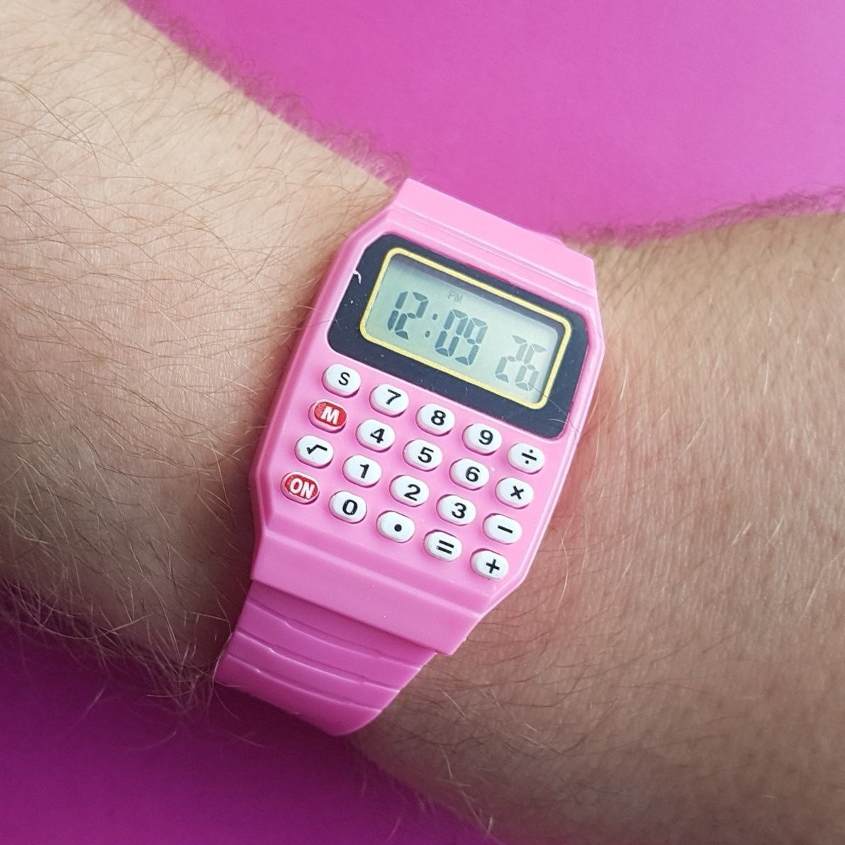
I like to call this my smart watch, as it can calculate numbers and show the time I found this calculator watch on aliexpress for under 3 Euros and intend to replace the PCB featuring an ARM chip, mainly to learn stuff. The LCD stays and I want to find out how to connect it.
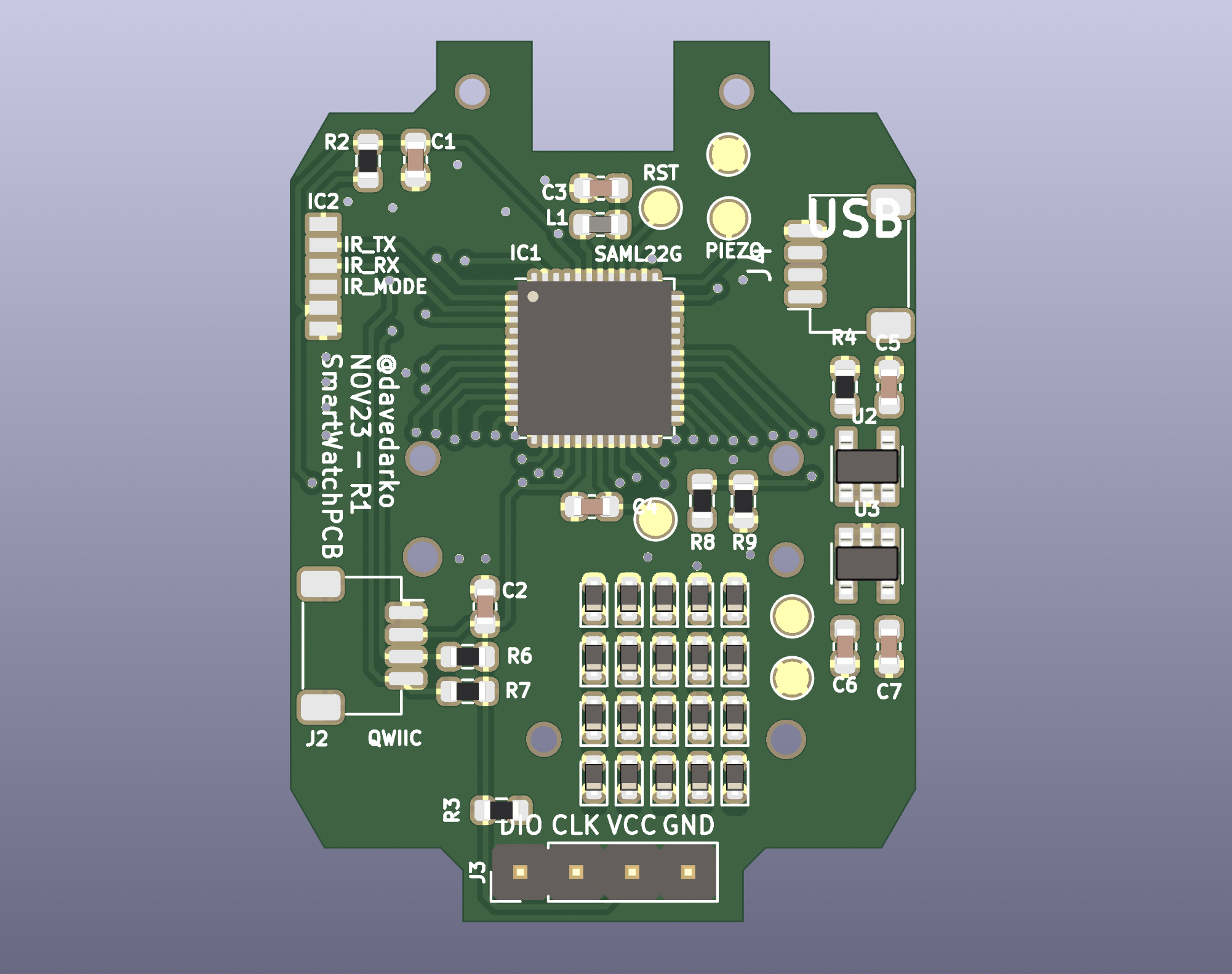
New PCB For Calculator Watch | rev1
2023-11-16 18:27:20
The first version was doomed from the beginning, since I had no diodes on the keys. I also swapped the USB micro socket with a JST-SH socket and made a small adapter board instead. Let's see how far I get this time.
The first version was doomed from the beginning, since I had no diodes on the keys. I also swapped the USB micro socket with a JST-SH socket and made a small adapter board instead. Let's see how far I get this time.
The first version was doomed from the beginning, since I had no diodes on the keys. I also swapped the USB micro socket with a JST-SH socket and made a small adapter board instead. Let's see how far I get this time.
The first version was doomed from the beginning, since I had no diodes on the keys. I also swapped the USB micro socket with a JST-SH socket and made a small adapter board instead. Let's see how far I get this time.
The first version was doomed from the beginning, since I had no diodes on the keys. I also swapped the USB micro socket with a JST-SH socket and made a small adapter board instead. Let's see how far I get this time.
The first version was doomed from the beginning, since I had no diodes on the keys. I also swapped the USB micro socket with a JST-SH socket and made a small adapter board instead. Let's see how far I get this time.
The first version was doomed from the beginning, since I had no diodes on the keys. I also swapped the USB micro socket with a JST-SH socket and made a small adapter board instead. Let's see how far I get this time.
The first version was doomed from the beginning, since I had no diodes on the keys. I also swapped the USB micro socket with a JST-SH socket and made a small adapter board instead. Let's see how far I get this time.
The first version was doomed from the beginning, since I had no diodes on the keys. I also swapped the USB micro socket with a JST-SH socket and made a small adapter board instead. Let's see how far I get this time.
The first version was doomed from the beginning, since I had no diodes on the keys. I also swapped the USB micro socket with a JST-SH socket and made a small adapter board instead. Let's see how far I get this time.
The first version was doomed from the beginning, since I had no diodes on the keys. I also swapped the USB micro socket with a JST-SH socket and made a small adapter board instead. Let's see how far I get this time.
The first version was doomed from the beginning, since I had no diodes on the keys. I also swapped the USB micro socket with a JST-SH socket and made a small adapter board instead. Let's see how far I get this time.
The first version was doomed from the beginning, since I had no diodes on the keys. I also swapped the USB micro socket with a JST-SH socket and made a small adapter board instead. Let's see how far I get this time.
The first version was doomed from the beginning, since I had no diodes on the keys. I also swapped the USB micro socket with a JST-SH socket and made a small adapter board instead. Let's see how far I get this time.
The first version was doomed from the beginning, since I had no diodes on the keys. I also swapped the USB micro socket with a JST-SH socket and made a small adapter board instead. Let's see how far I get this time.
The first version was doomed from the beginning, since I had no diodes on the keys. I also swapped the USB micro socket with a JST-SH socket and made a small adapter board instead. Let's see how far I get this time.
The first version was doomed from the beginning, since I had no diodes on the keys. I also swapped the USB micro socket with a JST-SH socket and made a small adapter board instead. Let's see how far I get this time.
The first version was doomed from the beginning, since I had no diodes on the keys. I also swapped the USB micro socket with a JST-SH socket and made a small adapter board instead. Let's see how far I get this time.
The first version was doomed from the beginning, since I had no diodes on the keys. I also swapped the USB micro socket with a JST-SH socket and made a small adapter board instead. Let's see how far I get this time.
The first version was doomed from the beginning, since I had no diodes on the keys. I also swapped the USB micro socket with a JST-SH socket and made a small adapter board instead. Let's see how far I get this time.