LEDodecahedron
We're going for it now, 612 LEDs, 51 of them controlled by a single IS31FL3733 chip
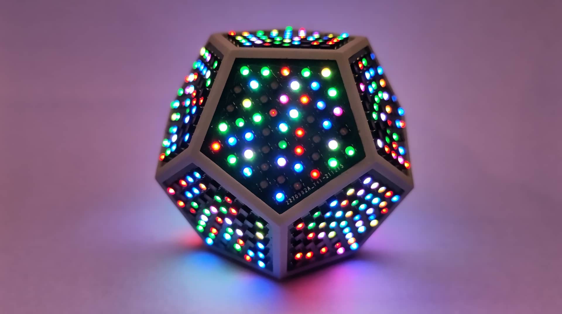
Bunch of IS31FL3733 on a pentagon PCB controlling a bunch (76? - 106? - 128? - 181?) of RGB LEDs. It's 51. Was hard enough to route anyways!
LEDodecahedron | silly idea
2024-09-24 14:36:37
since the IS31FL3733 is not recommended for new designs, why not redesign the LED PCBs with the IS31FL3741. gotta research that - would mean more LEDs (117 instead of 64).
According to my table, I would get 2 more rows around the cube with 106 LEDs.
There's only one ADDR pin here, so you can have a maximum of 4 panel adresses, but definitely managable to address half a cube with the RP2040 that has two I2C channels.