Portable Raspberry PI Zero | I2C on an Attiny85
2017-01-01 22:47:50
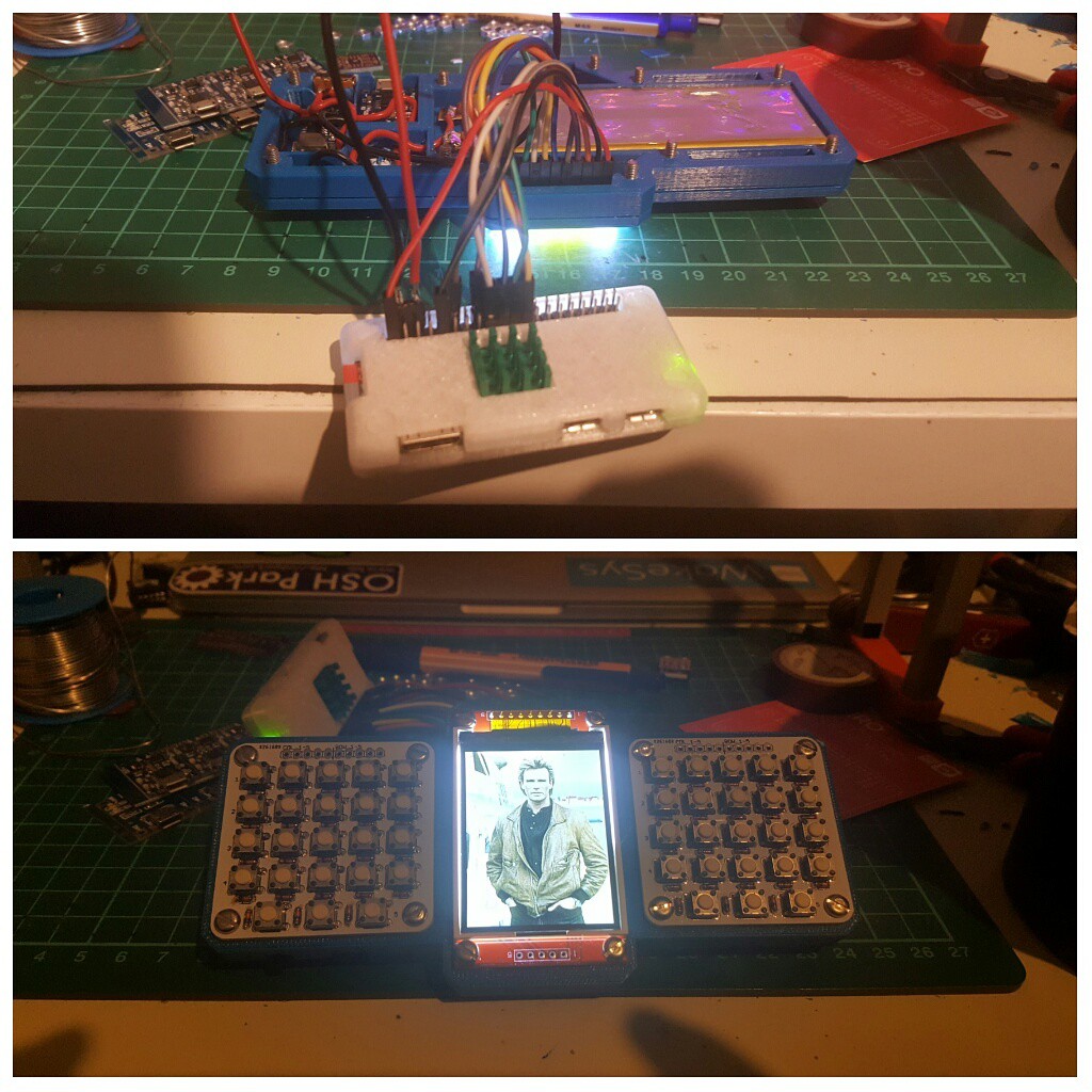
So I thought I would just add the Attiny85 family to the boards by adding the following link to my Additional Boards Manager URLs in my Arduino 1.6.9 IDE and get away with it and use the wire library to hack a little LED PWM backlight controller together. But since that didn't work for the tone() lib on the #Nyan Board , why would it here?
https://raw.githubusercontent.com/damellis/attiny/ide-1.6.x-boards-manager/package_damellis_attiny_index.json
So I then look around and find this library on GitHub https://github.com/rambo/TinyWire and with it's help I was able to whip together the LED controller! The idea here is that the pin 3 is connected to the PI and when toggled will write the PWM to pin 4. This PWM value can be set via I2C address 0x04.
#define I2C_SLAVE_ADDRESS 0x4
#include <TinyWireS.h>
int pwm_value = 127;
#ifndef TWI_RX_BUFFER_SIZE
#define TWI_RX_BUFFER_SIZE ( 16 )
#endif
void setup() {
TinyWireS.begin(I2C_SLAVE_ADDRESS);
TinyWireS.onReceive(receiveEvent);
pinMode(3, INPUT);
pinMode(4, OUTPUT);
}
void loop() {
TinyWireS_stop_check();
writeLed();
}
void writeLed()
{
if (digitalRead(3) == HIGH)
{
analogWrite(4, pwm_value);
}
else
{
digitalWrite(4, LOW);
}
}
void receiveEvent(uint8_t howMany)
{
if (howMany < 1)
{
return;
}
if (howMany > TWI_RX_BUFFER_SIZE)
{
return;
}
TinyWireS.receive();
howMany--;
if (!howMany)
{
return;
}
while(howMany--)
{
pwm_value = TinyWireS.receive();
}
}Portable Raspberry PI Zero | I2C on an Attiny85
2017-01-01 22:47:50
So I thought I would just add the Attiny85 family to the boards by adding the following link to my Additional Boards Manager URLs in my Arduino 1.6.9 IDE and get away with it and use the wire library to hack a little LED PWM backlight controller together. But since that didn't work for the tone() lib on the #Nyan Board , why would it here?
https://raw.githubusercontent.com/damellis/attiny/ide-1.6.x-boards-manager/package_damellis_attiny_index.json
So I then look around and find this library on GitHub https://github.com/rambo/TinyWire and with it's help I was able to whip together the LED controller! The idea here is that the pin 3 is connected to the PI and when toggled will write the PWM to pin 4. This PWM value can be set via I2C address 0x04.
#define I2C_SLAVE_ADDRESS 0x4
#include <TinyWireS.h>
int pwm_value = 127;
#ifndef TWI_RX_BUFFER_SIZE
#define TWI_RX_BUFFER_SIZE ( 16 )
#endif
void setup() {
TinyWireS.begin(I2C_SLAVE_ADDRESS);
TinyWireS.onReceive(receiveEvent);
pinMode(3, INPUT);
pinMode(4, OUTPUT);
}
void loop() {
TinyWireS_stop_check();
writeLed();
}
void writeLed()
{
if (digitalRead(3) == HIGH)
{
analogWrite(4, pwm_value);
}
else
{
digitalWrite(4, LOW);
}
}
void receiveEvent(uint8_t howMany)
{
if (howMany < 1)
{
return;
}
if (howMany > TWI_RX_BUFFER_SIZE)
{
return;
}
TinyWireS.receive();
howMany--;
if (!howMany)
{
return;
}
while(howMany--)
{
pwm_value = TinyWireS.receive();
}
}