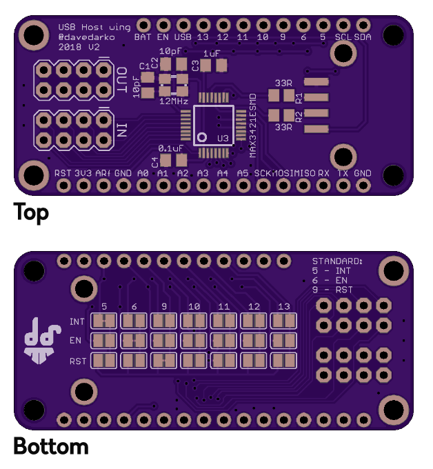
I still need to make this work / compile with all the feathers, sounds like a good software project for my vacation, right? The PCB could get got an update too, all 8 inputs and 8 outputs on a header.
I still need to make this work / compile with all the feathers, sounds like a good software project for my vacation, right? The PCB could get got an update too, all 8 inputs and 8 outputs on a header.
I still need to make this work / compile with all the feathers, sounds like a good software project for my vacation, right? The PCB could get got an update too, all 8 inputs and 8 outputs on a header.
I still need to make this work / compile with all the feathers, sounds like a good software project for my vacation, right? The PCB could get got an update too, all 8 inputs and 8 outputs on a header.
I still need to make this work / compile with all the feathers, sounds like a good software project for my vacation, right? The PCB could get got an update too, all 8 inputs and 8 outputs on a header.
I still need to make this work / compile with all the feathers, sounds like a good software project for my vacation, right? The PCB could get got an update too, all 8 inputs and 8 outputs on a header.
I still need to make this work / compile with all the feathers, sounds like a good software project for my vacation, right? The PCB could get got an update too, all 8 inputs and 8 outputs on a header.
I still need to make this work / compile with all the feathers, sounds like a good software project for my vacation, right? The PCB could get got an update too, all 8 inputs and 8 outputs on a header.
I still need to make this work / compile with all the feathers, sounds like a good software project for my vacation, right? The PCB could get got an update too, all 8 inputs and 8 outputs on a header.
I still need to make this work / compile with all the feathers, sounds like a good software project for my vacation, right? The PCB could get got an update too, all 8 inputs and 8 outputs on a header.
I still need to make this work / compile with all the feathers, sounds like a good software project for my vacation, right? The PCB could get got an update too, all 8 inputs and 8 outputs on a header.
I still need to make this work / compile with all the feathers, sounds like a good software project for my vacation, right? The PCB could get got an update too, all 8 inputs and 8 outputs on a header.
I still need to make this work / compile with all the feathers, sounds like a good software project for my vacation, right? The PCB could get got an update too, all 8 inputs and 8 outputs on a header.
I still need to make this work / compile with all the feathers, sounds like a good software project for my vacation, right? The PCB could get got an update too, all 8 inputs and 8 outputs on a header.
I still need to make this work / compile with all the feathers, sounds like a good software project for my vacation, right? The PCB could get got an update too, all 8 inputs and 8 outputs on a header.
I still need to make this work / compile with all the feathers, sounds like a good software project for my vacation, right? The PCB could get got an update too, all 8 inputs and 8 outputs on a header.
I still need to make this work / compile with all the feathers, sounds like a good software project for my vacation, right? The PCB could get got an update too, all 8 inputs and 8 outputs on a header.
I still need to make this work / compile with all the feathers, sounds like a good software project for my vacation, right? The PCB could get got an update too, all 8 inputs and 8 outputs on a header.
I still need to make this work / compile with all the feathers, sounds like a good software project for my vacation, right? The PCB could get got an update too, all 8 inputs and 8 outputs on a header.
I still need to make this work / compile with all the feathers, sounds like a good software project for my vacation, right? The PCB could get got an update too, all 8 inputs and 8 outputs on a header.
I still need to make this work / compile with all the feathers, sounds like a good software project for my vacation, right? The PCB could get got an update too, all 8 inputs and 8 outputs on a header.