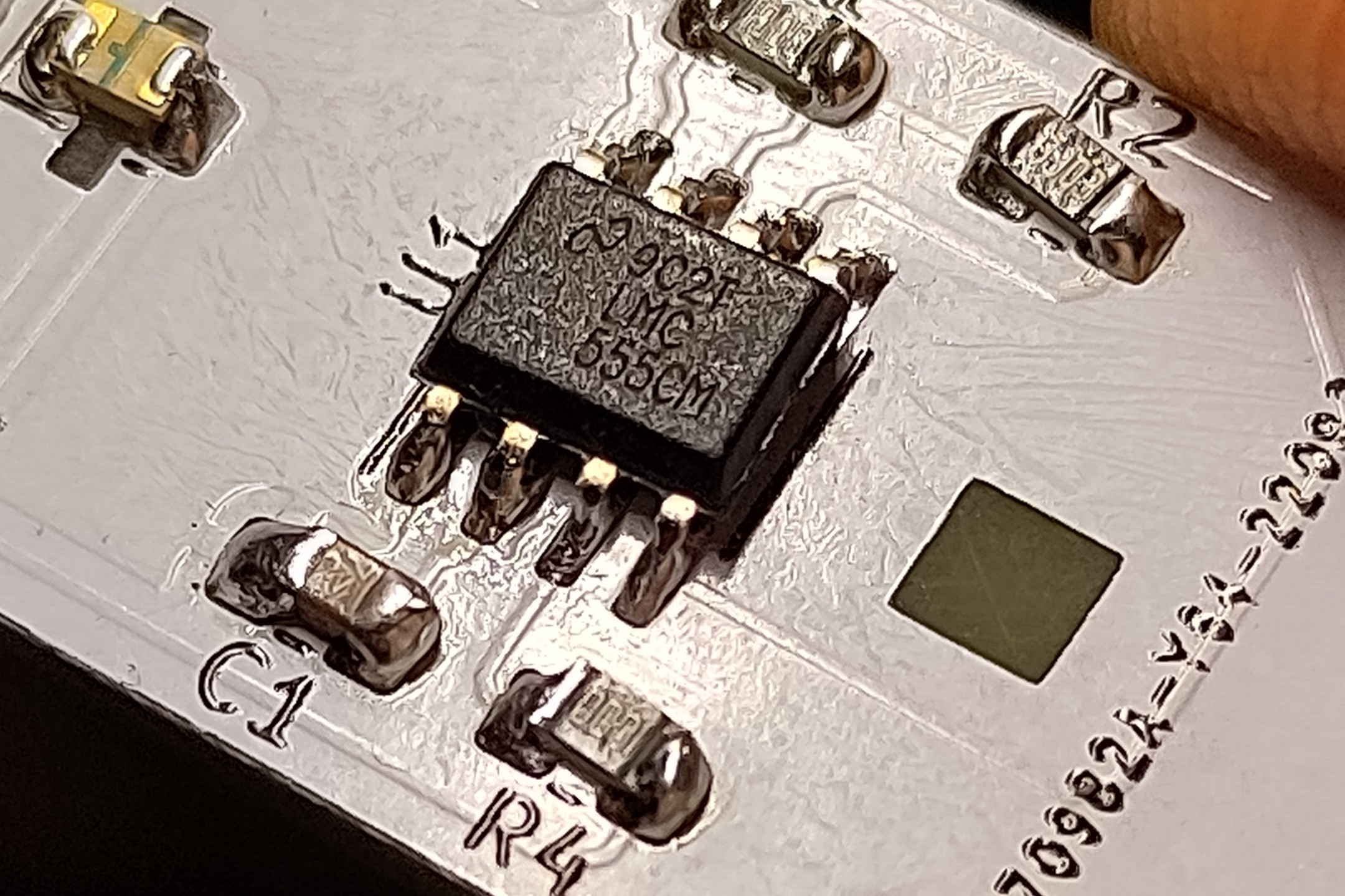
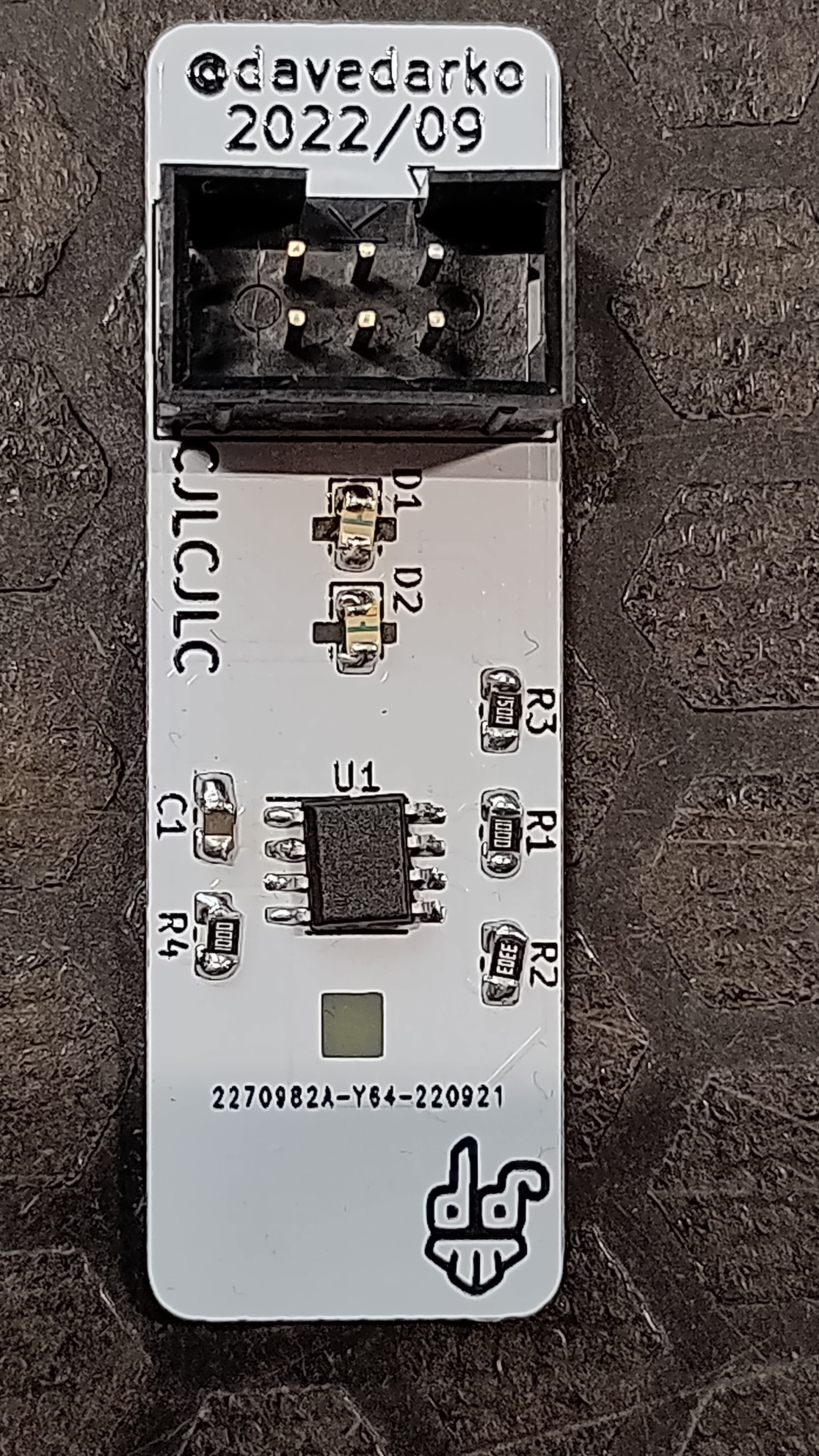
First off all, I am very sorry for giving you a bag with freely flying resistors in it and that you have to read the value in the darkness of Congress! In parts this is @Alex 's fault, he once gave me bags of 0805 resistors and I recycled them in this projects, as I only want to use 0603 parts most of the time.
Anywho, there might be a 330k resistor in there instead of a 390k resistor, so according to this fine website, it should blink 3 times per second, instead of 2 times.
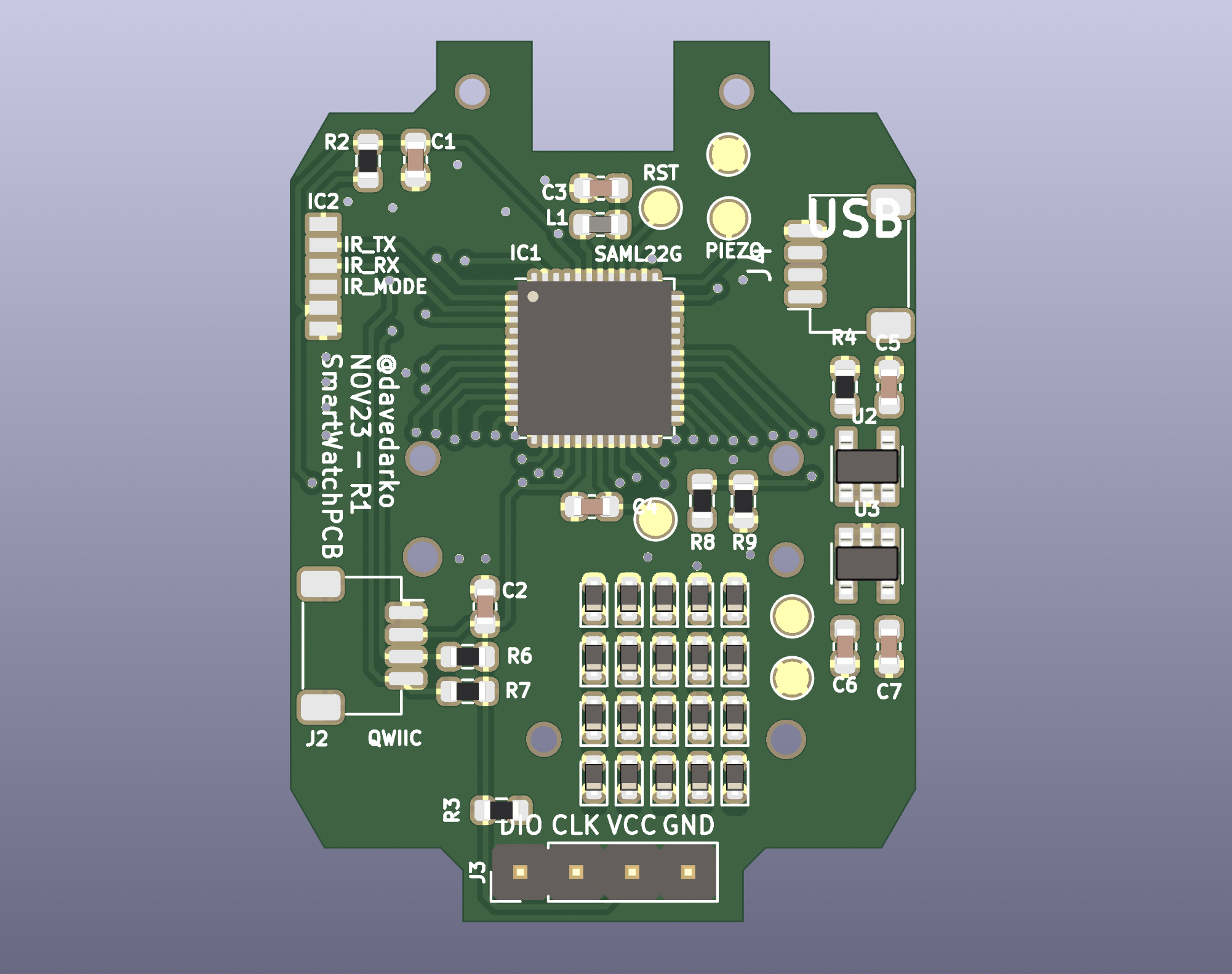
The first version was doomed from the beginning, since I had no diodes on the keys. I also swapped the USB micro socket with a JST-SH socket and made a small adapter board instead. Let's see how far I get this time.
The first version was doomed from the beginning, since I had no diodes on the keys. I also swapped the USB micro socket with a JST-SH socket and made a small adapter board instead. Let's see how far I get this time.
The first version was doomed from the beginning, since I had no diodes on the keys. I also swapped the USB micro socket with a JST-SH socket and made a small adapter board instead. Let's see how far I get this time.
The first version was doomed from the beginning, since I had no diodes on the keys. I also swapped the USB micro socket with a JST-SH socket and made a small adapter board instead. Let's see how far I get this time.
The first version was doomed from the beginning, since I had no diodes on the keys. I also swapped the USB micro socket with a JST-SH socket and made a small adapter board instead. Let's see how far I get this time.
The first version was doomed from the beginning, since I had no diodes on the keys. I also swapped the USB micro socket with a JST-SH socket and made a small adapter board instead. Let's see how far I get this time.
Me building projects from hackaday.io | Supercon 23 badge
2023-10-28 23:24:14
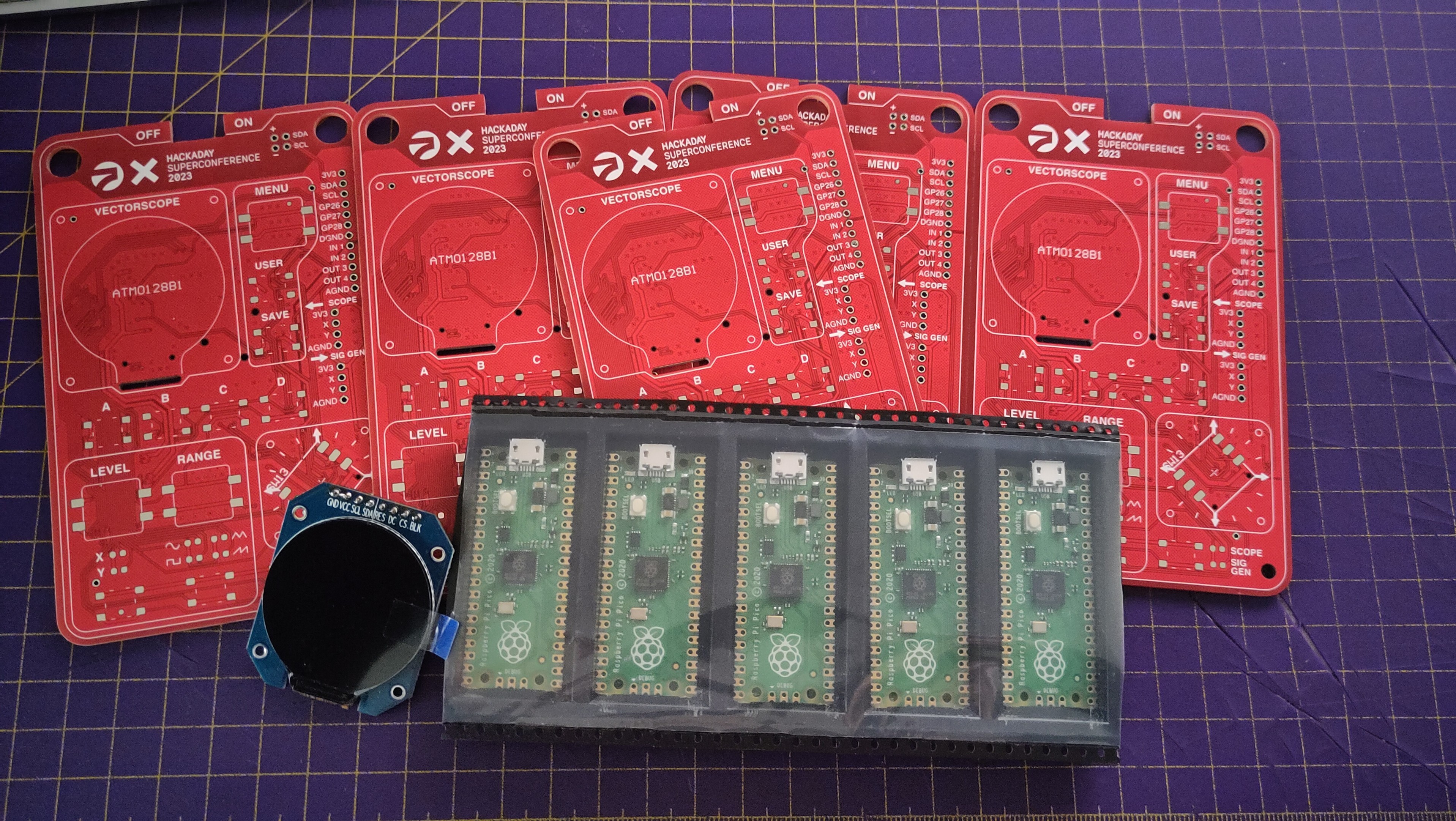
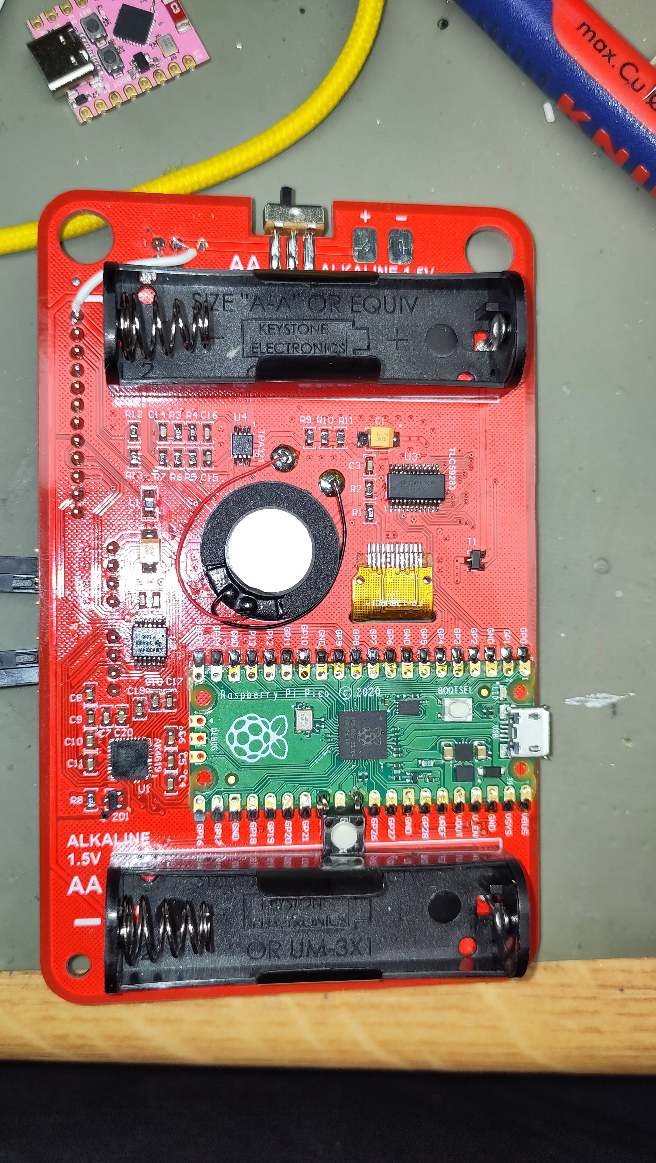
Don't have all parts yet, but enough to get started. I've send two PCBs to @Alex as well - but I have a head start ;)
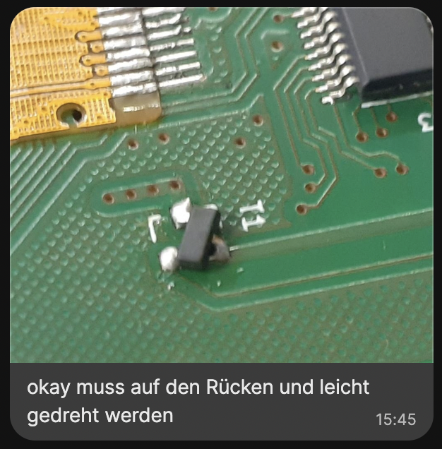
We had to figure out some errata ourselves, since we've ordered boards that weren't the final version apparently. The BOM itself is also different now. The MOSFET in our version had to be soldered on in dead-bug style and turned by some degrees.
The badge worked in the end and I did two small modifications: the simple add-on was powered from the batteries, I changed that to also get 3.3V from the regulator. There was also a good use-case for an additional reset button, so I did that.
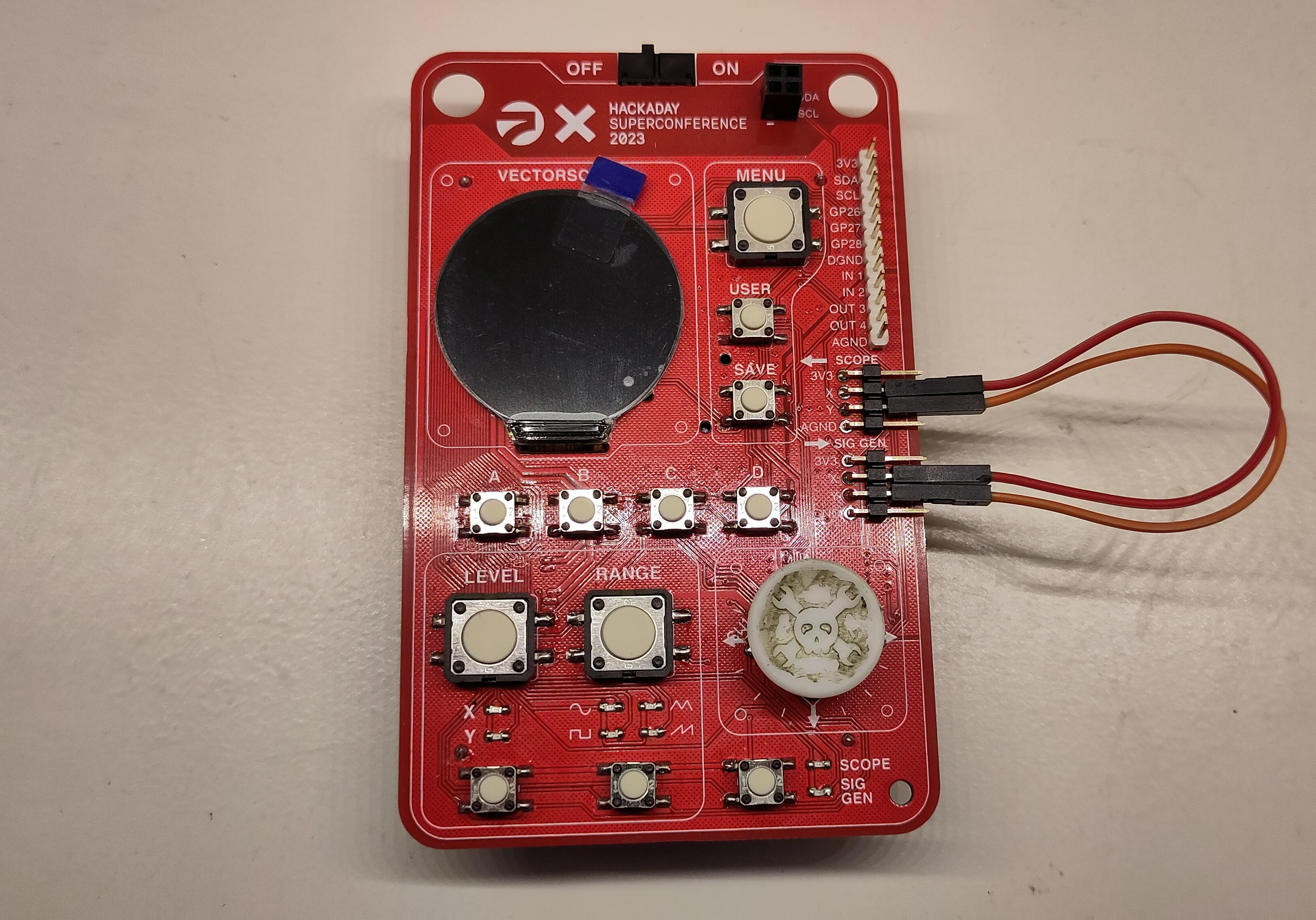
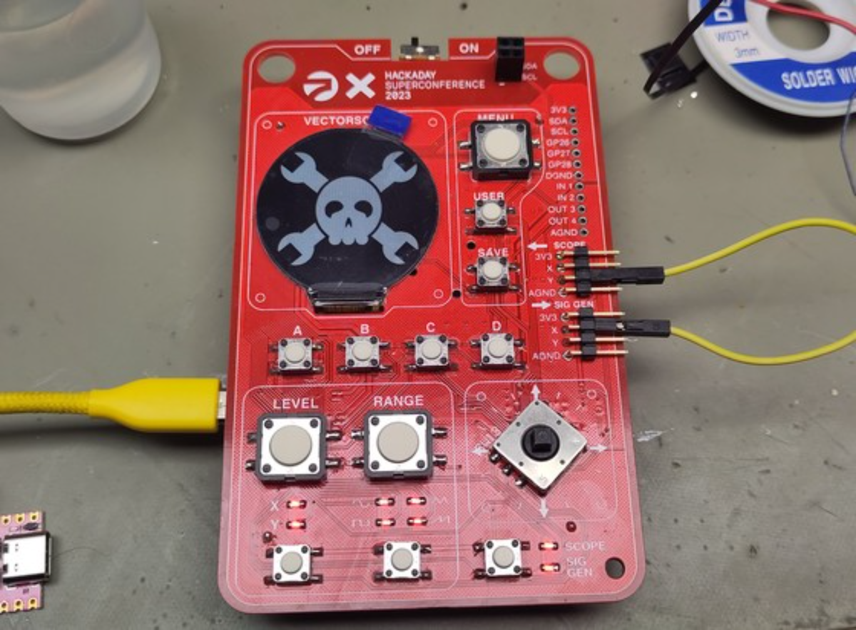
The badge worked great after the latest firmware was pushed on it, very happy with the result!
The 3d printed buttons arrived from JLCPCB, a long with the expander PCB, so this is complete now :)
Me building projects from hackaday.io | Supercon 23 badge
2023-10-28 23:24:14
Don't have all parts yet, but enough to get started. I've send two PCBs to @Alex as well - but I have a head start ;)
We had to figure out some errata ourselves, since we've ordered boards that weren't the final version apparently. The BOM itself is also different now. The MOSFET in our version had to be soldered on in dead-bug style and turned by some degrees.
The badge worked in the end and I did two small modifications: the simple add-on was powered from the batteries, I changed that to also get 3.3V from the regulator. There was also a good use-case for an additional reset button, so I did that.
The badge worked great after the latest firmware was pushed on it, very happy with the result!
Been a minute and I've currently found some motivation to work on animations and make the code run faster plus also mapping things finally.
Found out the ESP32 only has a 64 byte hardware buffer for I2C and that I need to use endTransmission after 63 bytes, stole some adafruit code for I2C oled displays and put it in the library I'm currently using for the IS31FL3733.