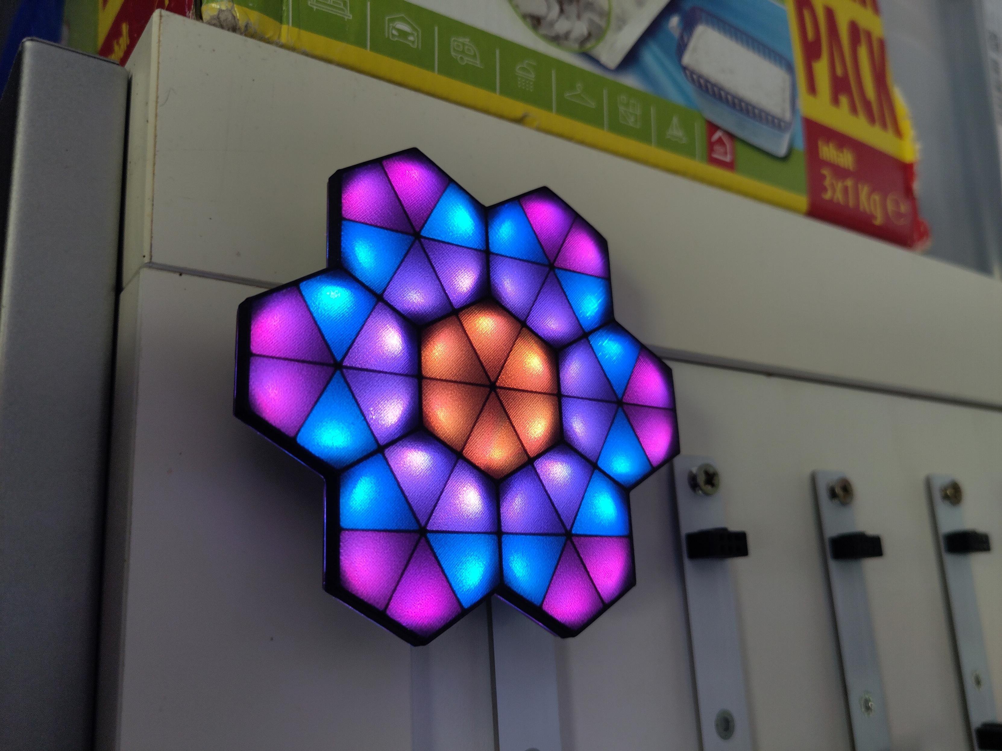
hexagonal neopixel tiles | Smol Version with 42 LEDs
2026-05-28 20:39:54
I have a CH32V003 version.with 42 LEDs now and could not get Arduino to work with it before. I now looked into it again and am very close to uploading to the SAO from Arduino.
First I had to make the compiling for the Adafruit_Neopixel library work. There's an issue with the hardware flag. You have to change the library slightly to work with the arduino core.
Change anything in .c and .h filefrom
defined(ARDUINO_ARCH_CH32)
to this:
defined(ARDUINO_ARCH_CH32) || defined(CH32V00x)
Then I had to change some doubles to floats variables, hopefully all the libs still work. Also added a const to the fixed variables to move them to Program Flash.
The Arduino compiler is missing a flag for the CH32V003 to run with the internal 48MHz oscillator - something I later noticed by testing the hackaday CH32V003 supercon addon with a simple 1sec blink sketch. Reading this issue I thought it was fixed, but the blink don't lie. So following the issue I added the following flag to the compiler steps. This will basically break compiling for every other CH32 chip though, so be aware.
Uploading with the linux computer works, but with my mac I run into a libusb problem, that complains about the installed libusb architecture of my computer being wrong. After a few "chatGPT tells me to install new homebrew versions with rosetta" episodes I just gave up. You can also just upload the binary file you can export from arduino onto the CH32V003 by using minichlink.
./minichlink -w whateverfile.ino.bin flash
Side note: I had to again update the LED arrangement array
price tag project boxes | and I'm reverting to analog lol
2026-05-07 11:49:02
So long story short, the tags were awesome, but somehow they lost the image data after a bit or the data on the server got compromised somehow. This project felt too static for displays that can easily update daily or more with fresh data, so I'm okay with that. Already found a good home for them, at least a home with money to spend on them.
hexagonal neopixel tiles | revived for congress 38C3
2024-12-24 20:53:45
We needed some decorations for congress and I remembered that I have these PCBs flying around somewhere. Too bad I couldn't find all 50 PCBs, so I came up with making some with LED strings as well - with folding the strip carefully, you just have to solder the cable on.